4G Vs. 5G Key Technology Differences


In this article, I will address and review the Key technology differences between 4G and 5G; I believe reading this topic is crucial, especially if you have a good background in 4G and have just started your 5G studying. This article will cover the differences between 4G & 5G for the following
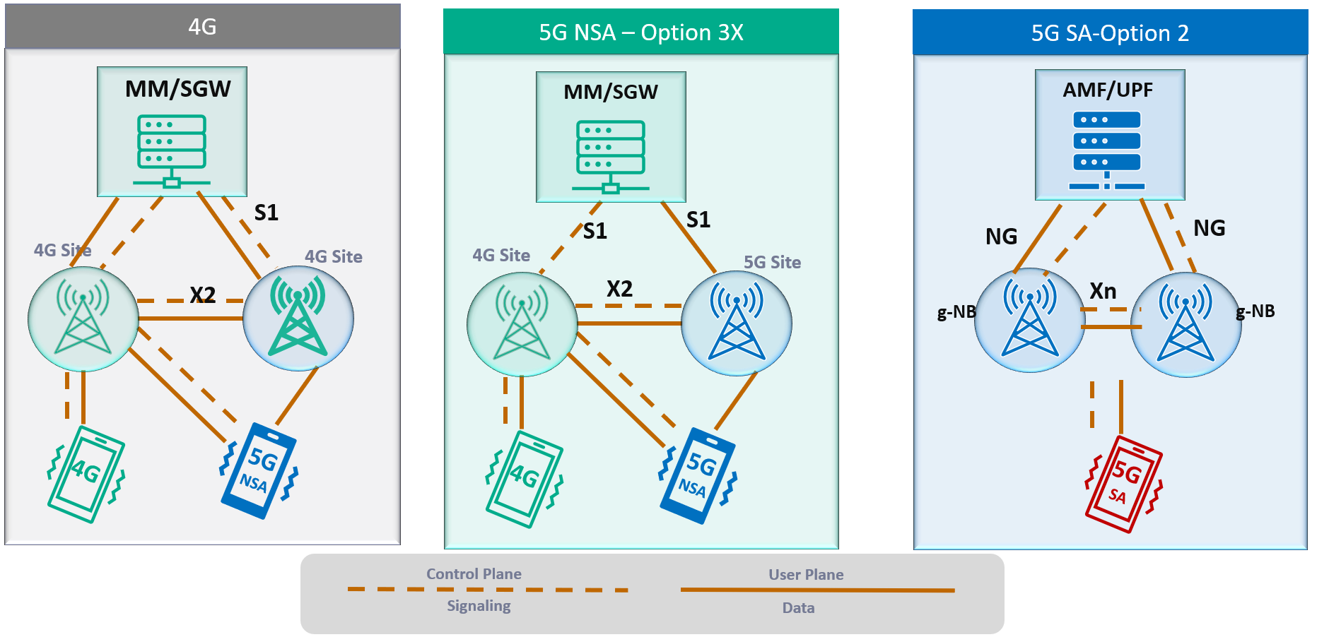
RAN Structure: 4G, 5G NSA & 5G SA
From the Radio Access Network side, the overall structure looks very similar, for example:
- X2 interface connecting different 4G Nodes was replaced by Xn interface.
- S1 interface connecting BTS Side to the Core network replaced by Ng interface.
- MME replaced by AMF and SGW-U and PGW-U replaced by UPF.
- Some functions of the PGW have been transferred to the AMF, while others have been moved to the UPF, as will be explained in the following sections.
From a superficial view, it is a matter of naming change; however, there are subtle changes implemented that leads to huge improvement; we will be addressing one of the points which can lead to improving latency in 5G SA.
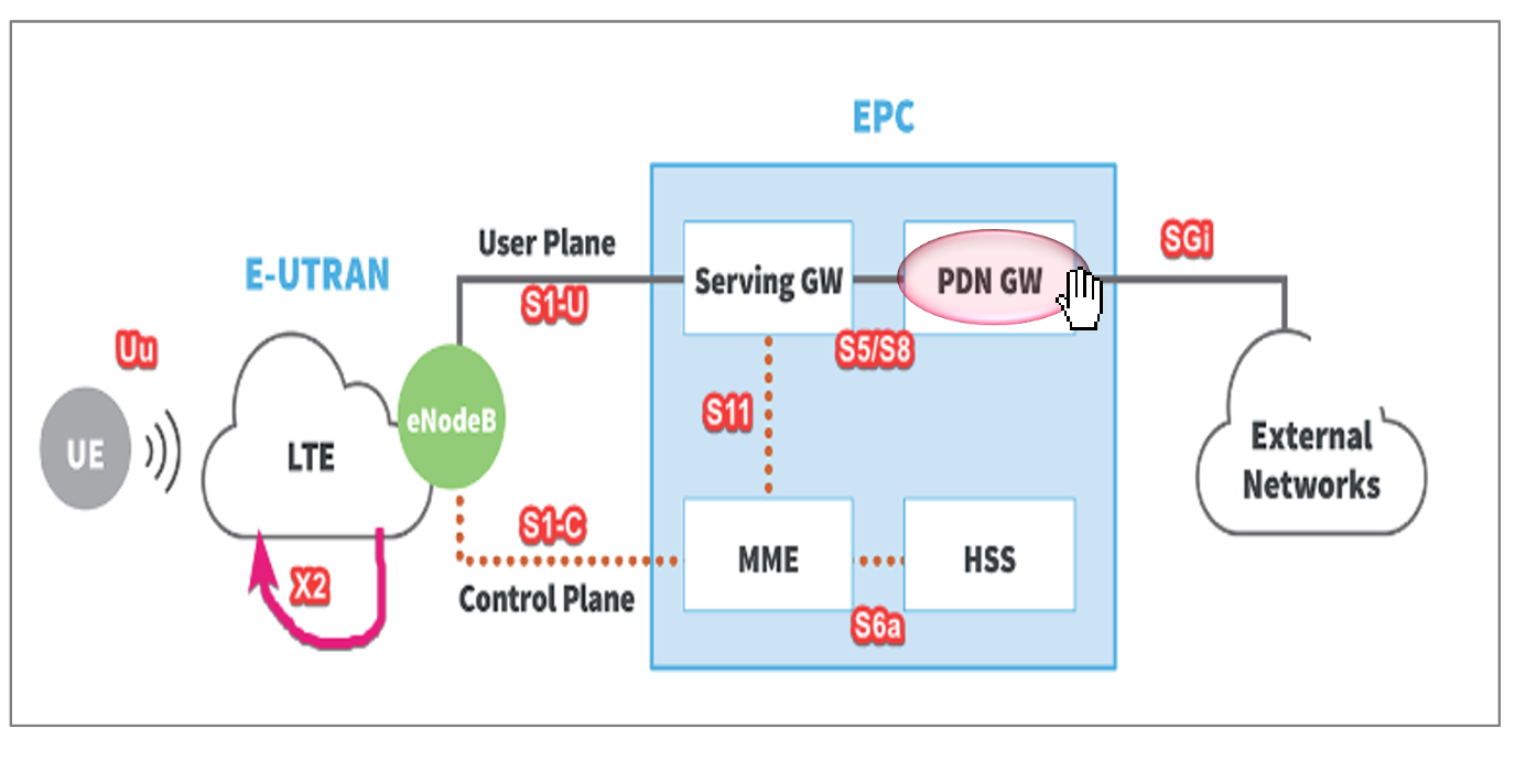
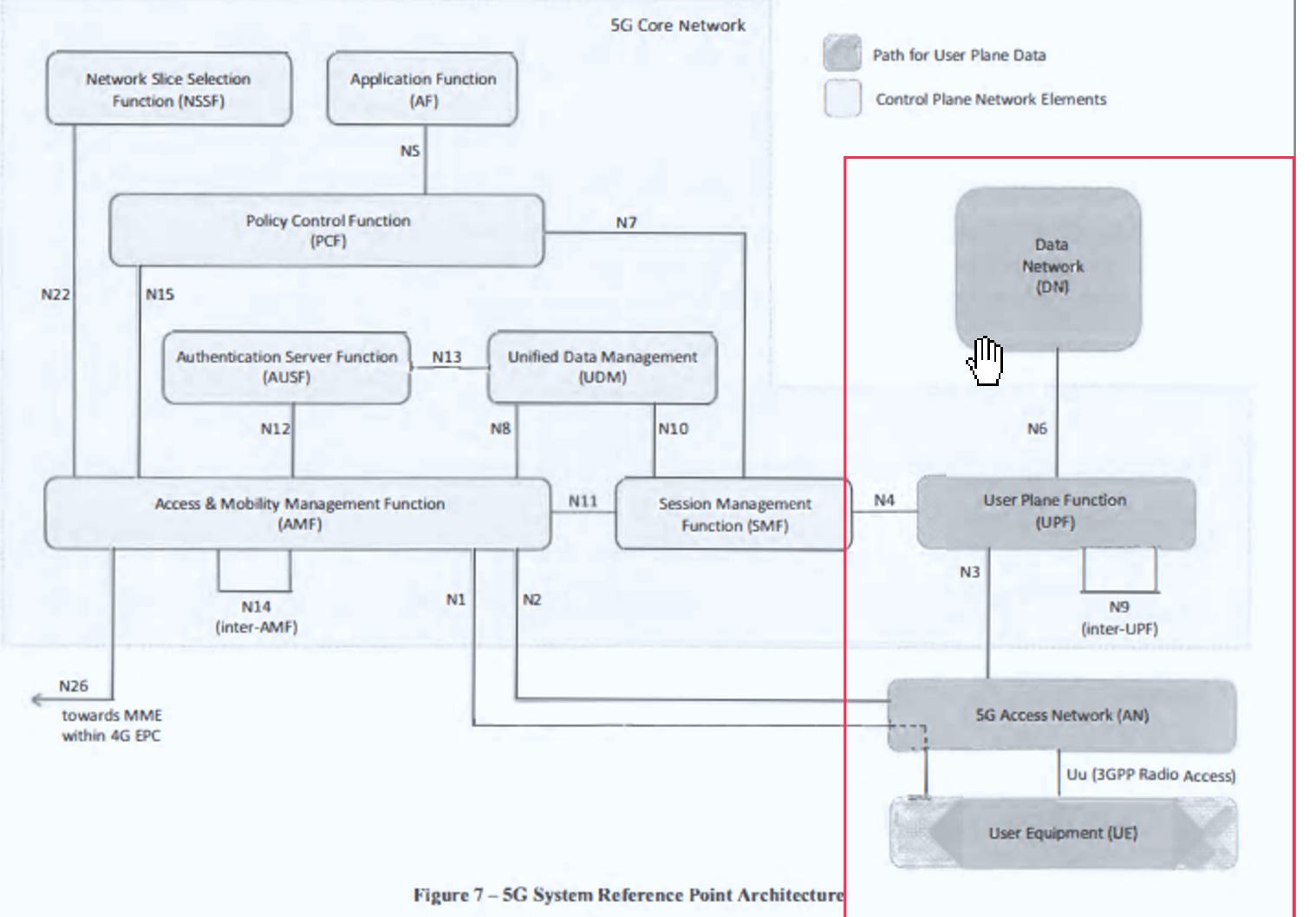
One of the main differences provided in 5G SA Architecture is that the User plane and Control function has separated; see below comments and the 4G & 5G Full Architecture for more details.
- An important Characteristic of the 5G System is separating the user plane and control plane functions, which differs from the original 4G System architecture in the following:
- In 4G: P-GW provides both control plane and user plane functions(IP Address allocation & Packet Forwarding)
- In 5G: SMF Provides IP Allocation, and UPF provides packet forwarding
2. User and Control plane separation allows independent scaling of the two functions
- Operators can add more user plane capabilities without having to add more control plane
- Minimize latency by distributing User plane and keeping it geographically close to the AN
Packet Gateway provides both User plane and Control Plane function in 4G
While in 5G, Only UPF provides User plane function.
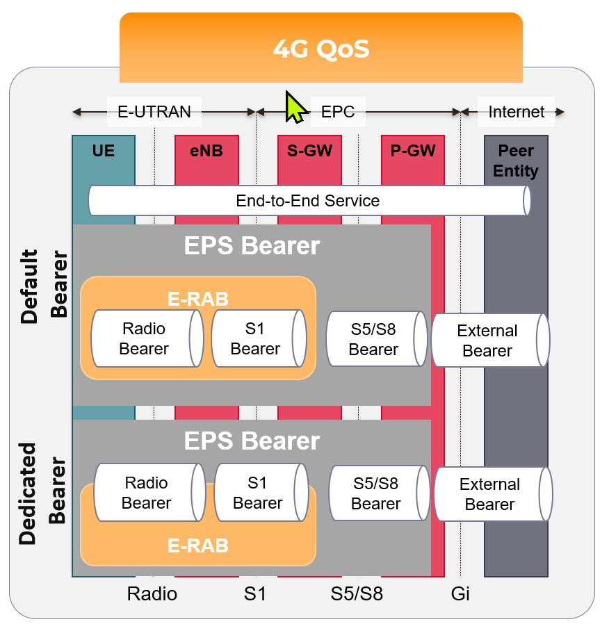
Quality of Service: 4G & 5G
For the QoS Part, there is an essential change in the way of how the QoS is being allocated.
- In 4G, EPS Bearer is responsible for providing E2E User Plane connectivity between the UE and Access Point Name "APN" within the Packet Gateway.
- The point here is that EPS Bearer has a one-to-one mapping to the QoS, This means that the User needs to establish a new EPS bearer every time there is a new QCI assignment, Only One QoS(Example QCI 9 can be assigned to one DRB) with no flexibility.
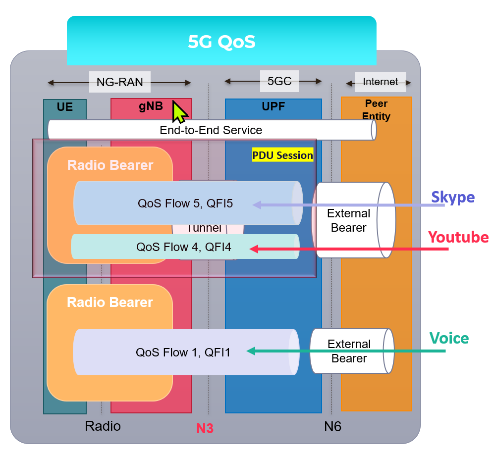
- In 5G, PDU Sessions is responsible for providing E2E User Plane connectivity between the UE and Data Network Name "DNN" within the User Plane Function ( UPF)
- However, Unlike 4G EPS Bearer, PDU Session supports one or more QoS Flows, Which means that QoS Flow to radio bearer mapping is not necessarily one-to-one mapping and multiple QoS can be mapped to the same Radio Bearer.
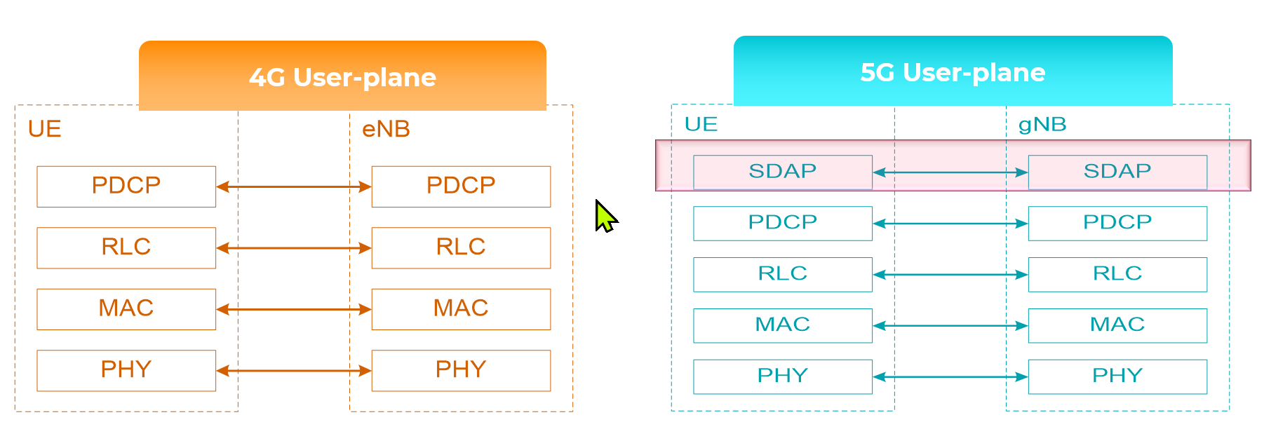
Radio Protocol Stack: 4G & 5G
SDAP Primary Task:
- Service Data Application Protocol (SDAP) is responsible for mapping QoS bearers to radio bearers according to their quality-of-service requirements. This protocol layer is not present in LTE but introduced in NR when connecting to the 5G core network due to the new quality-of-service handling
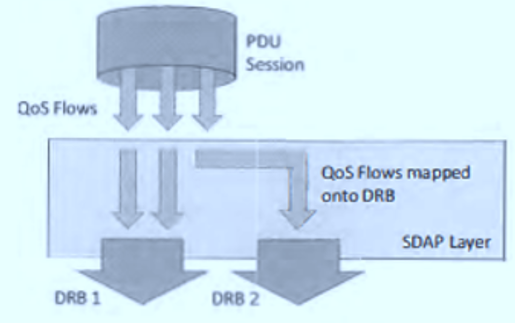
- The new SDAP (Service Data Adaptation Protocol) primary function maps each QoS Flow onto a specific Data Radio Bearer
- Multiple QoS Flows can be mapped onto a single DRB or,
- Single QoS Flow can be mapped onto a single DRB.
Overall Technology Comparison
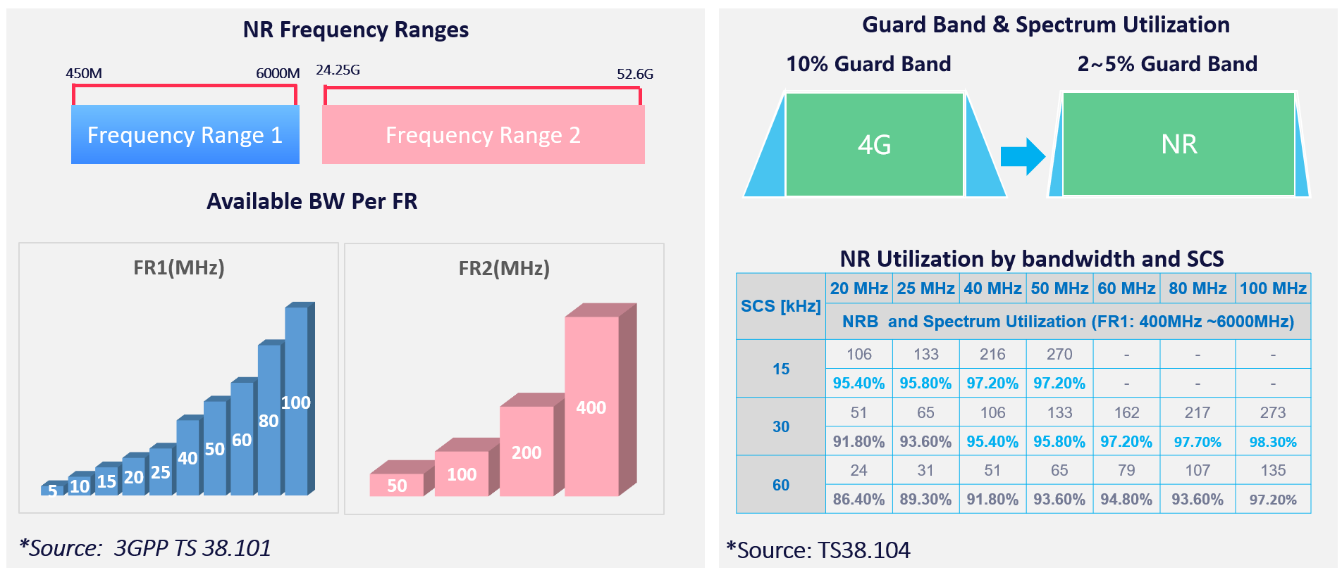
(1) 4G Vs. 5G Bandwidth
- 4G Supports a maximum up to 20Mhz BW, While 5G is up to 400Mhz
- 5G offers less Guard Band(2~5) and Higher Spectrum Utilization(Utilizing up to 95% of the Channel BW, While 4G Utilize 90%)
- Up to 20x Higher Bandwidth and New Spectrum Definition. (ex. mmwave)
- NR Offers Less Guard-band and Higher spectrum utilization
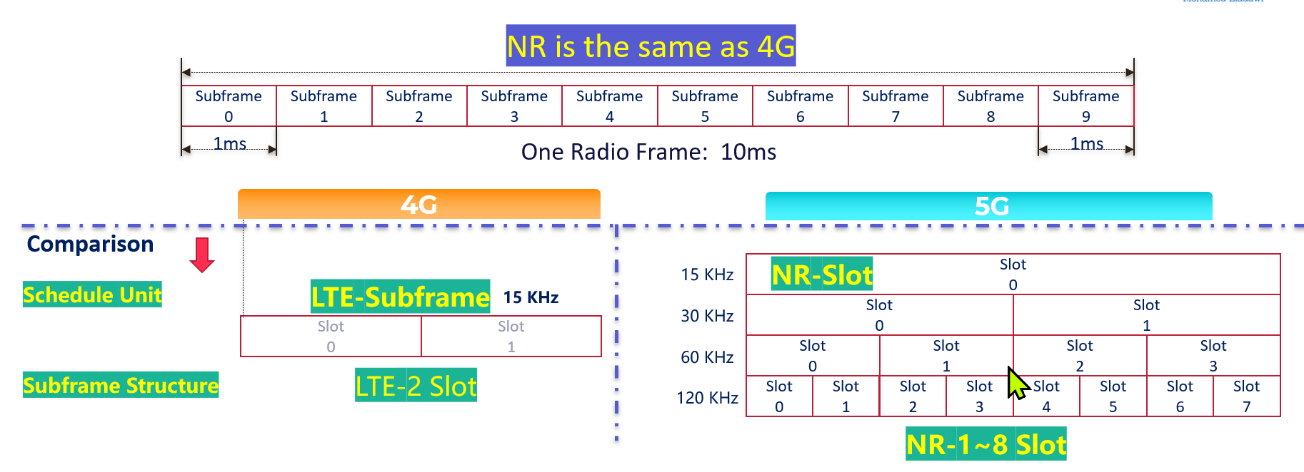
(2) Frame Structure Comparison: 4G & 5G
The following summarized the main differences between 4G & 5G Frame Structure
- Frame and Subframe duration remained the Same for 5G
- Number of Symbols in a slot is now fixed to 14 in 5G (4G is fixed to 7)
- 5G has a flexible numerology, which allows different configurations as the Slot Duration relies on SCS(Sduration = 1 /SCS)
- 5G is now using a Slot as a scheduling Unit instead of Sub-frame compared to 4G
- NR RB Resource Grid is double 4G(14 vs. 7 OFDM symbols in one RB )
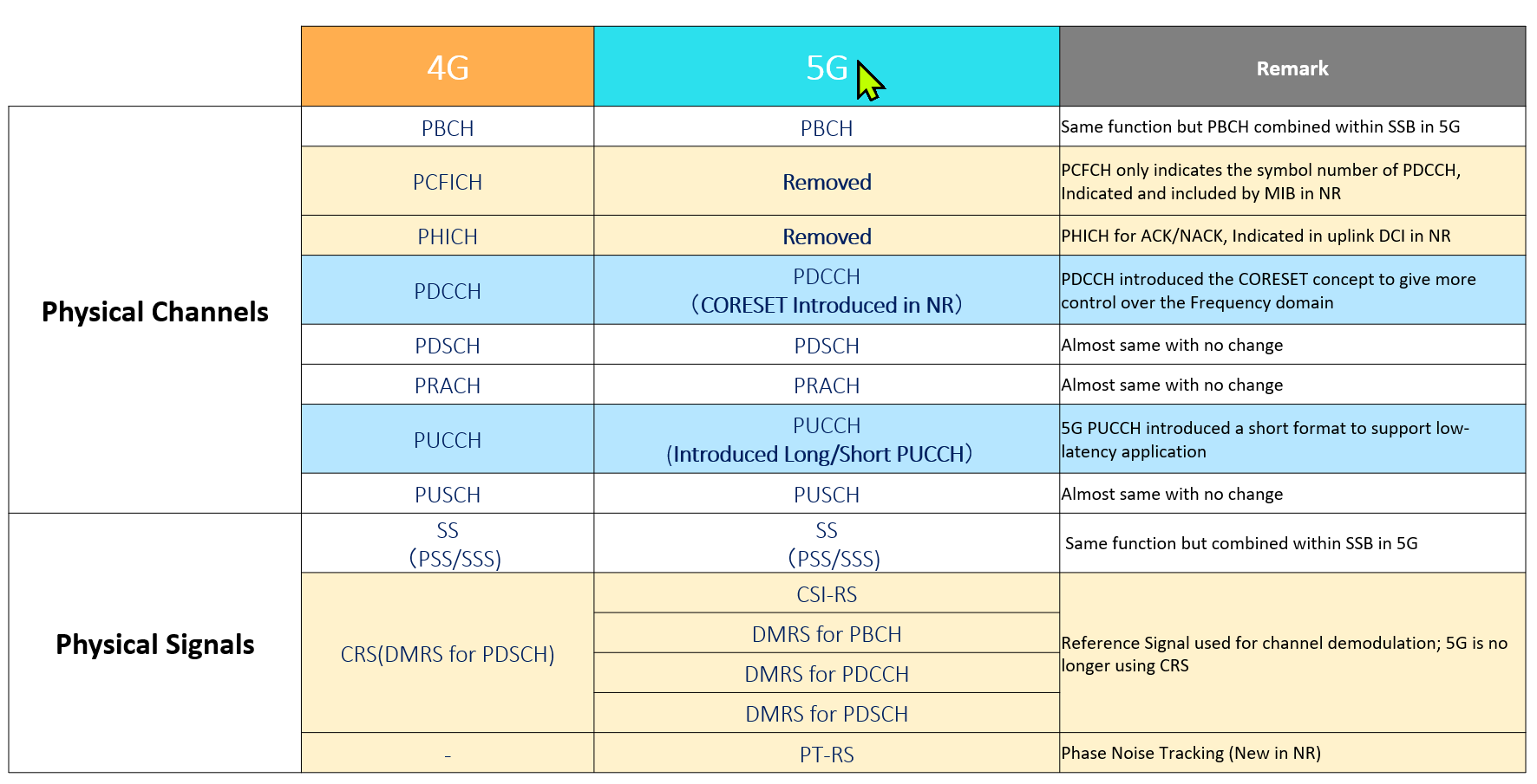
(3) Physical Channel & Signals Comparison : 4G & 5G
The below table summarizes the main differences in Physical Channel and Signals
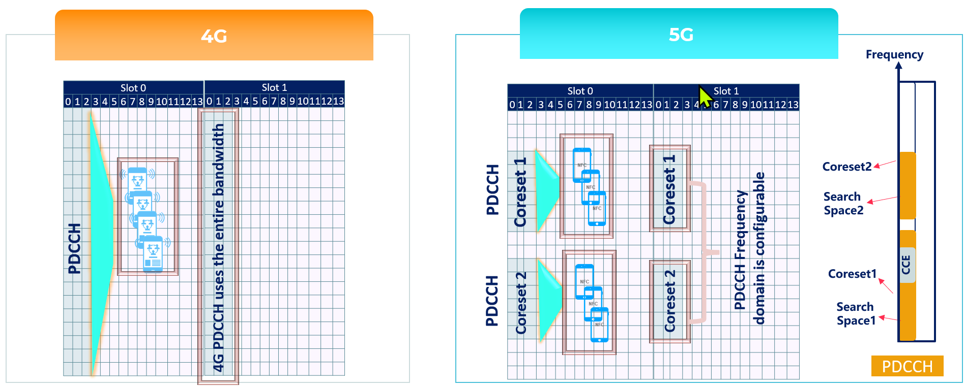
A- Downlink Comparison: Physical Downlink Control Channel(PDCCH)
- In LTE, PDCCH control channels are always distributed across the entire system bandwidth.
- NR PDCCHs are designed to transmit in a configurable control resource set (Called CORESET).
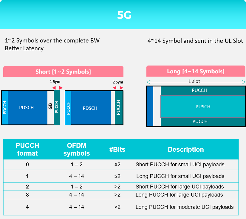
B- Uplink Comparison: Physical Uplink Control Channel(PUCCH)
- In 4G, PUCCH is transmitted in one or more Physical Resource Blocks (PRB) at the edges of the system bandwidth and is only supporting Long-Format(duration 1 ms)
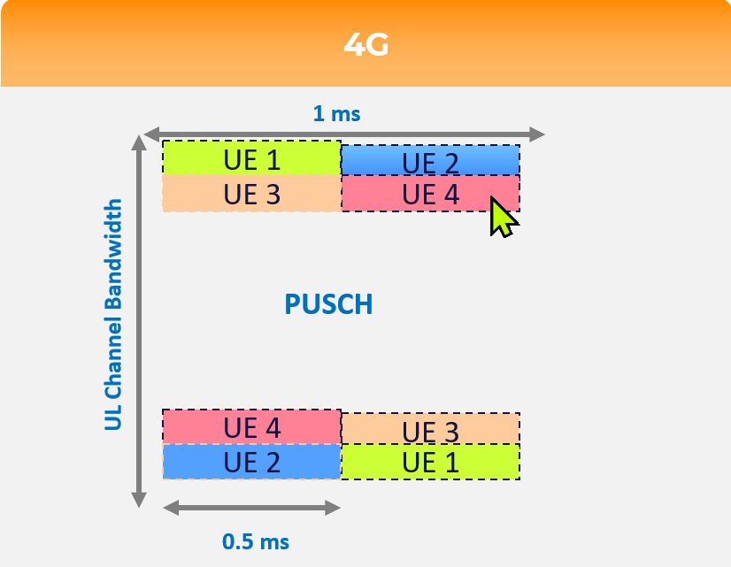
While 5G supports both Long and short format, Where short format provides the following:
- 1~2 Symbols over the complete
- Provides Better Latency
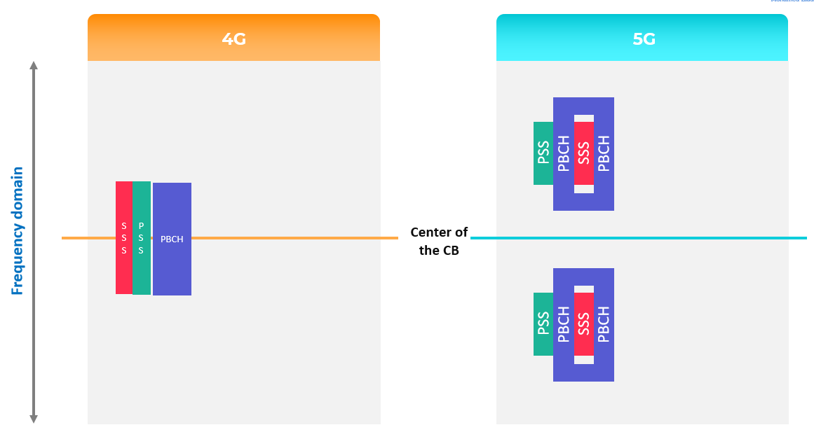
C- PBCH & Synchronization Signals: 4G & 5G
- There are 2 main changes in PBCH and SS compared to 4G:
- PBCH and SS are now being combined into SSB
- SSB Frequency domain location is flexible and can be configured at different locations based on the network requirements(4G PBCH & SS are fixed at the center of Channel BW)
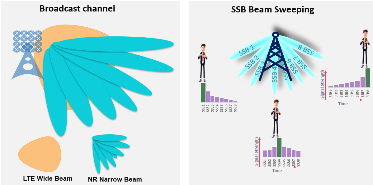
D- Broadcast Channel Comparison: 4G & 5G
- 4G Provide Wide Beam coverage, while 5G provides narrow beam coverage for broadcast channels, which can improve the Coverage and Quality
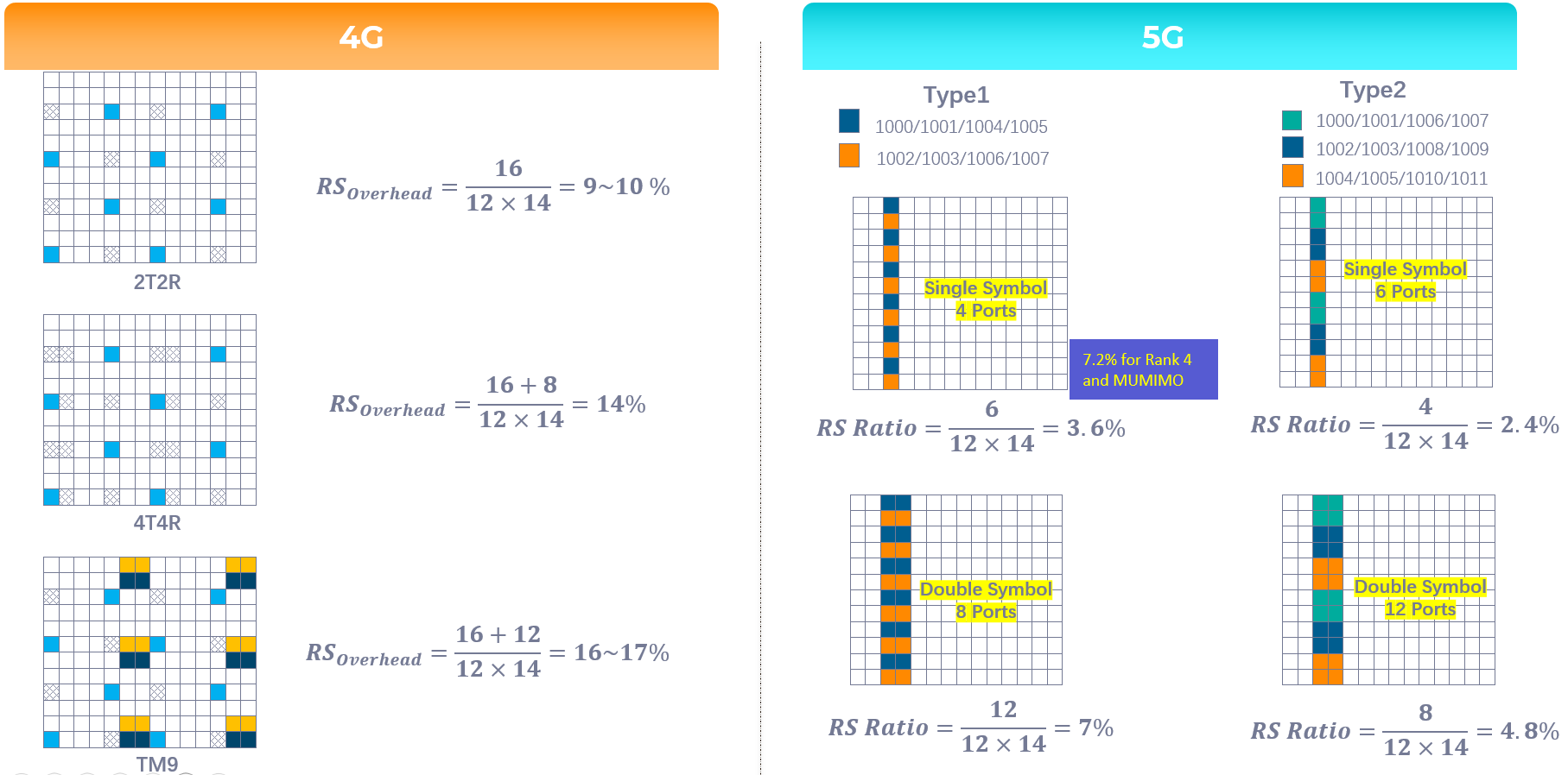
E- Reference Signal Overhead comparison: 4G & 5G
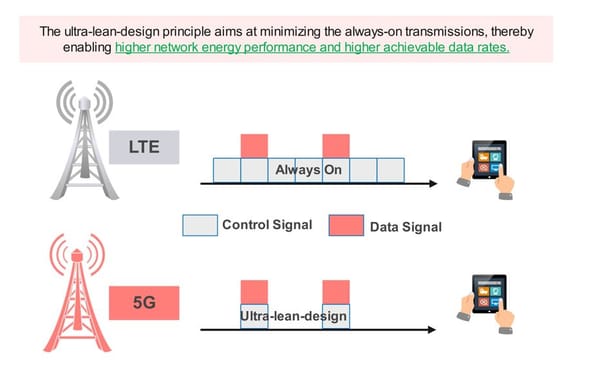
- 5G Overhead is almost half 4G, and the mean reason behind that 5G has no Cell Specific Reference Signal as 4G
- As you know that CRS was all the time transmitted "Always on" over the entire BW and consume a large number of resource elements within the Resource block
- While 5G uses DMRS for channel demodulation instead of CRS.
- PDSCH DMRS offers much less overhead compared to CRS due to the following:
- DMRS is transmitted within the set of RBs allocated to PDSCH. i.e, if a UE is allocated 10RBs for PDSCH, then both PDSCH and DMRS will be transmitted across those BW
- DMRS Configuration type 1 uses 6 RS within one or two symbols, which add around 3.6% up to 7% overhead to 5G, while 4G offers from 9% to 17% overhead. Please see the below picture for more details and refer to the below-attached video for more information.
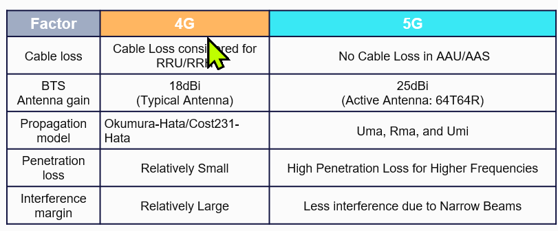
Key differences in Link Budgets: 4G & 5G
4G & 5G almost have the same Link Budget Basic Methodology
Link Budget is counting all of the gains and losses from the TX through the medium(Free Space, Cables, etc.) to the receiver
Simple Link Budget Equation:
•Received Power(dBm) = TX Power(dBm) + Gains - Losses
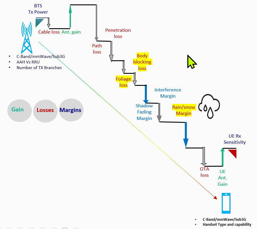
Main consideration:
Below Video for the same:
Sources:
- 5G NR in Bullets
- 3GPP TS 38.101 & TS38.104