5G DL Transmit Power Design- Article

Introduction:
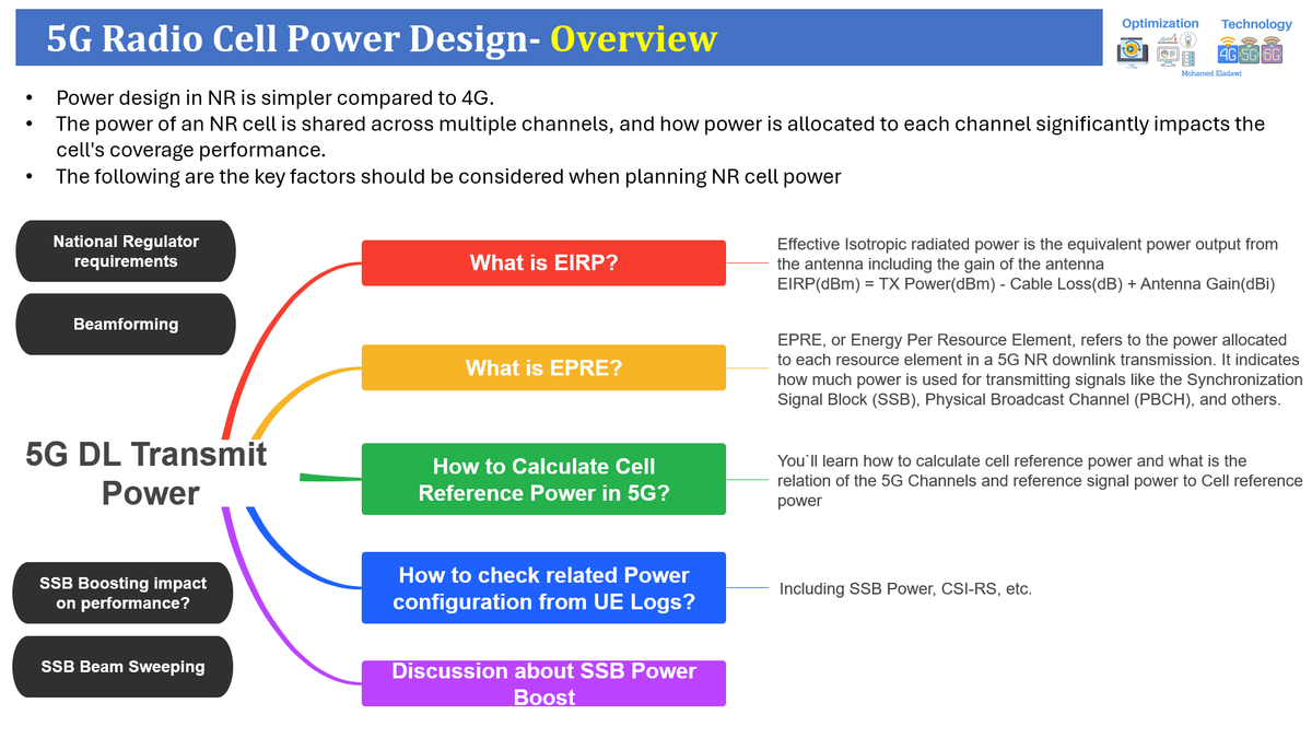
In general, power design in NR is simpler than in 4G. In NR, a cell's power is shared across multiple channels, and the allocation of power to each channel plays a crucial role in determining the cell's coverage performance. This article discusses the key aspects of 5G DL Transmit Power Design, which should be considered when planning NR cell power.
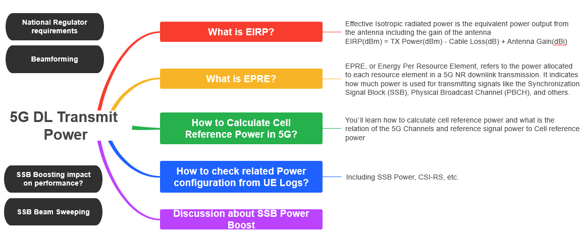
- What is EIRP?
- How to Calculate Cell Reference Power in 5G?
- How is Channel Power Calculated? i.e (SSB Power)
- SSB Power Boosting impact on throughput(PDSCH)
- 3GPP Power Parameters Description
(1) What is EIRP?
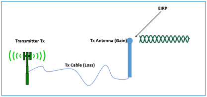
- EIRP stands for Effective Isotropic radiated power which is the equivalent power output from the antenna including the gain of the antenna and then deducing the cable loss.
- EIRP(dBm) = TX Power(dBm) - Cable Loss(dB) + Antenna Gain(dBi)
💡
In simpler terms, EIRP is the actual power radiated from the antenna, taking into account the transmitter power, antenna gain, and any losses in the system.
Why is EIRP important, and what are its use cases in the telecom domain?
EIRP (Effective Isotropic Radiated Power) is important in the telecom domain because it determines the effective power radiated by an antenna, which directly impacts coverage, signal strength, and interference management.
Use cases include: (The second point is especially important for operators)
- Coverage Planning: Ensuring sufficient signal strength in target areas.
- Regulatory Compliance: Meeting power limits set by telecom authorities.
- Interference Control: Minimizing interference with neighboring cells or systems.
- Link Budget Analysis: Calculating the performance of a communication link.
💡
EIRP is a critical parameter for designing and optimizing wireless networks.
Summarized Explanation for EIRP in Passive and Active Antenna Systems:
- Passive Antenna Systems:
- Formula: EIRP=PTx+GAntenna−LLoss−AMIMO
- where PTx: Transmit power (dBm), GAntenna: Antenna gain (dBi), LLoss: Cable/connector loss (dB), AMIMO: MIMO adjustment (e.g., 3 dB for 2x2, 6 dB for 4x4)
- Calculation: EIRP is derived by adding antenna gain to transmit power, subtracting losses, and adjusting for MIMO setups (e.g., -3 dB for 2x2, -6 dB for 4x4).
- Example: A 4x4 MIMO with 46 dBm transmit power, 18 dBi antenna gain, and 1 dB loss results in an EIRP of 69 dBm over 40 MHz.
- EIRP=46+18−1−6=69dBm
- Regulations: Some regions cap EIRP, such as 65 dBm per 5 MHz, which is equivalent to 74 dBm for 40 MHz bandwidth. (3dB is doubling the power)
- EIRP=65+10⋅log10(40/5)=74dBm over 40 MHz.
- Formula: EIRP=PTx+GAntenna−LLoss−AMIMO
- Active Antenna Systems (With Beamforming):
- In active antenna systems with beamforming, the same principles apply, but antenna gain depends on beamforming weights. For example, an antenna with 64 transmit paths (each at 26 dBm) results in 44 dBm total transmit power. With a 25 dBi directional beam, the EIRP reaches 69 dBm. Active antennas benefit by concentrating power in narrower beams, reducing intercell interference.
💡
TDD duty cycles can also be factored in when calculating average EIRP; for example, with 60% downlink, EIRP is reduced by (10*Log(0.6) = 2.2 dB.
(2) How to Calculate Cell Reference Power in 5G?
(1) Key Steps Before Calculating 5G Cell Reference Power
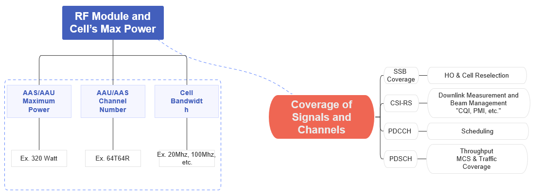
- Collect RF Module and Cell Max Power Information:
- Identify the type of antenna used (active or passive).
- Determine the maximum power capability of your hardware (e.g., 320 Watts, as shown in the example).
- Obtain Antenna Branch Information:
- Confirm the number of TX/RX branches (antenna branches) supported.
- Verify Bandwidth Details:
- Verify the currently supported bandwidth for the cell you plan to tune the power for. For example, if you upgrade the bandwidth from 40 MHz to 80 MHz, you will need to double the power to maintain the same coverage footprint.
Now, let's go into the details of how to calculate the cell reference power.
Simple Explanation of 5G Cell Reference Power
- In a 5G network, cell reference power is the baseline amount of power transmitted by a cell (or base station) across its coverage area.
- It's used to ensure that signals can be received clearly by devices within the cell's range. Think of it as the "starting point" for the cell's power output.
💡
Simple analogy: Imagine you’re speaking in a large room. The cell reference power is like your normal speaking volume—loud enough for people nearby to hear you clearly.
In technical terms:
- Cell reference power depends on factors like the cell's maximum hardware power, the bandwidth (number of resource blocks), and the network's configuration.
The formula used to calculate it:
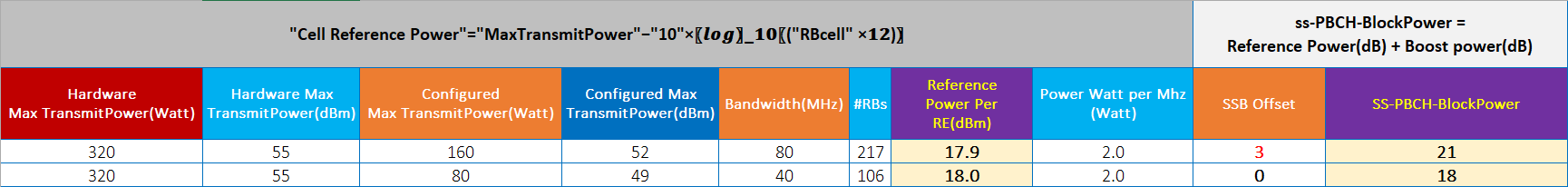
Cell Reference Power = MaxTransmitPower - 10 × log10(RB_cell × 12)- MaxTransmitPower: The maximum power output of each transmission channel.
- This is a configurable value that can be adjusted to modify the power. However, it is important to note that the final power calculation will never exceed the maximum hardware power limit.
- RB_cell: The number of resource blocks (RBs) allocated to the cell, determined by the cell’s bandwidth.
- 12: Represents the number of subcarriers per resource block.
- MaxTransmitPower: The maximum power output of each transmission channel.
- Once the cell reference power is set, it can be adjusted (boosted) for specific signals, like synchronization or broadcast signals, to improve their reach and clarity. This adjustment ensures consistent and efficient 5G network performance.
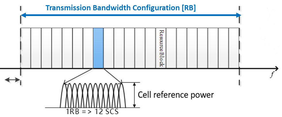
- The picture below illustrates how resource blocks (RBs) and subcarriers are arranged within the transmission bandwidth configuration. The Cell Reference Power corresponds to the power allocated across these RBs.
(3) How is Channel Power Calculated?
- Based on the cell reference power, the power for the NR (New Radio) cell channel can be calculated using an offset, below is an example of SSB Power calculation
- SS-PBCH-BlockPower = Cell Reference Power + Boost Power (in dB).
💡
Important Note: Increasing the SSB power may improve coverage but can negatively impact throughput. This is because boosting SSB power involves reallocating power from other PDSCH PRBs while ensuring that the total transmit power of the gNB stays within the configured maximum transmission limit. (This will be explained in detail in Section 4: SSB Power below)
- SS-PBCH Block Power refers to the power allocated to the Synchronization Signal - Physical Broadcast Channel (SS-PBCH) blocks, which are critical for the cell's operation. This power includes:
- The cell reference power as the baseline.
- Additional boost power to enhance the signal strength.
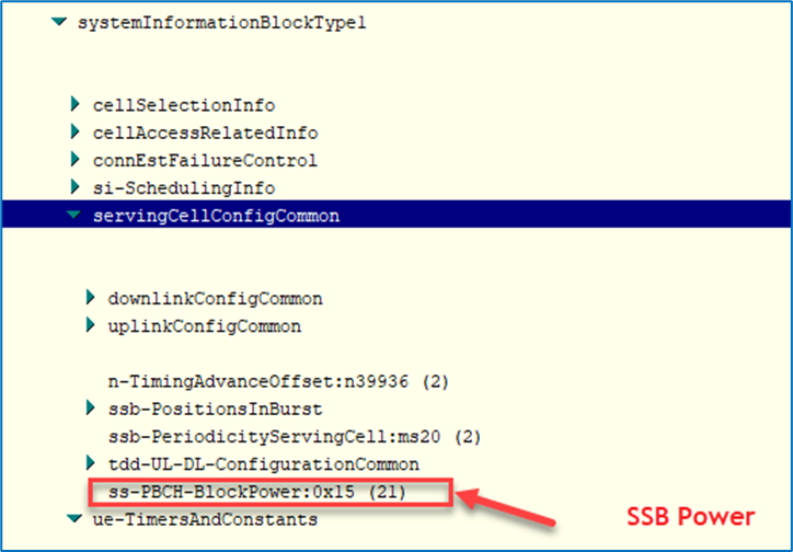
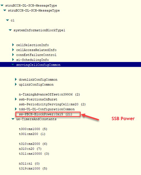
- Practical example for SSB Power calculation: Assume that the SSB Power Offset is 3 dB and the Cell Reference Power is 18 dB. This means the SSB Power equals 21 dB. As shown in the image below, this is how you can verify the current 5G SSB Power using drive test (DT) data through the configuration information provided for the SS-PBCH-BlockPower, which is part of the system information block (SIB) configuration for the serving cell.
Below are examples calculated using an Excel template, which is provided via a separate link at the end of this article. You can use this template as a reference for both Reference Power and SSB Power calculations.
(4) SSB Power Boosting impact on throughput(PDSCH)
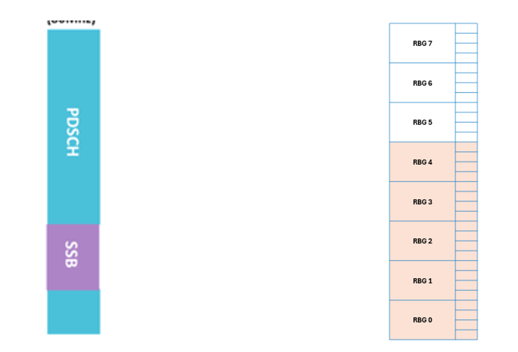
- Since SSB is transmitted over a subset of PRBs (20 PRBs), its power can be increased by borrowing power from other PDSCH PRBs, while ensuring the total transmit power of the gNB remains within the configured maximum transmission limit.
- This results in higher UE-measured RSRP and extended NR coverage.
- A larger value of SSB Power Boost parameter results in higher power used for sending an SSB, larger coverage of the SSB beam, and lower available transmit power for data transmitted at the same time.
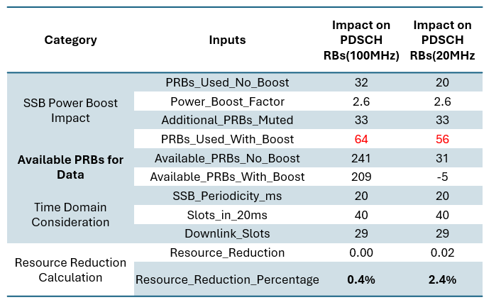
- Below is an estimation used to calculate the amount of resources reduced for PDSCH when the SSB Power is increased.
- As shown, the lower the bandwidth, the higher the resource reduction for PDSCH. For example, in a 100 MHz bandwidth, PDSCH RBs are reduced by approximately 0.4%, while in a 20 MHz bandwidth, they are reduced by around 2.4%. For more details, refer to the video shared at the end of this article.
💡
Increasing SSB power allows for faster setup and improved SCG radio resource coverage. However it might slightly reduce your throughput. There are typically two soft methods to extend SSB coverage: SSB power boost and TxPower increase.
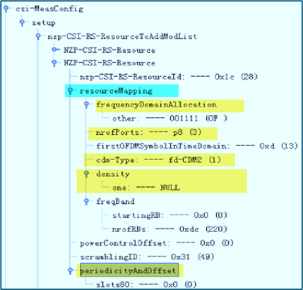
(5) 3GPP Power Parameters Description
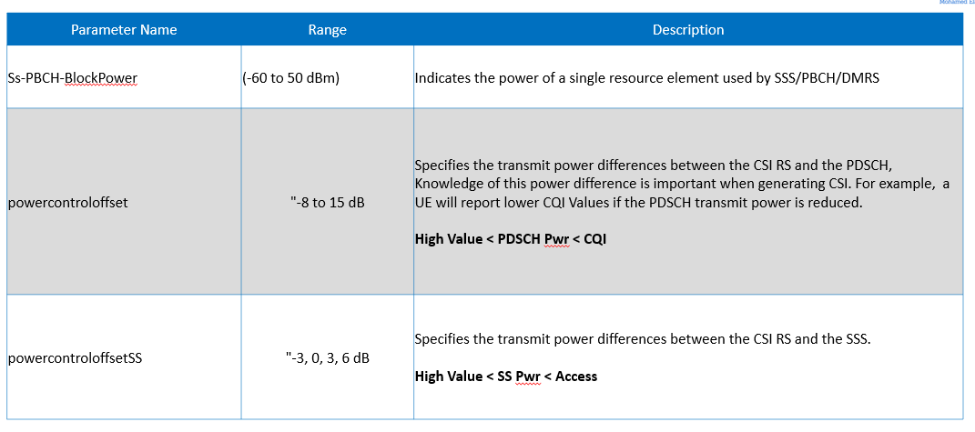
Layer 3 message:
Key Takeaways
- Cell Reference Power determines the baseline power for a 5G cell and depends on bandwidth, RBs, and hardware capabilities.
- SS-PBCH-BlockPower is a crucial parameter for enhancing signal strength, calculated by adding a boost power value to the cell reference power.
- Proper configuration of these values ensures optimal performance and coverage in 5G networks.
YouTube video for the same
Working Materials:
5G Downlink Power Design Simplified- Materials
Your Gateway to Mastering Telecom Foundations
Sources:
- 5G NR in Bullets
- 3GPP TS 38.214