5G NR Slot Format Deep Dive

Introduction
This article will cover the following topics:
- NR Slot Format – Introduction
- 4G Vs 5G TDD Subframe/Slot format:
- NR Slot Format Types Deep dive: Fixed, Semi-Static & Dynamic TDD
- Cross Link Interference definition and relation with NR Slot Allocation
- 4G/NR coexistence
- NR Slot Format Planning and design impact on the KPIs Performance
NR Slot Format – Introduction
- To provide highest possible flexibility, 5G NR supports various duplexing schemes such as Frequency Division Duplex (FDD), Time Division Duplex (TDD), Semi-static TDD and Dynamic TDD.
- LTE also supported both TDD and FDD, but unlike the single frame structure used in NR, LTE used two different frame structure types used.
- Furthermore, unlike LTE where the uplink-downlink allocation does not change over time, the TDD operation for NR is designed with dynamic TDD as a key technology component.
- 3GPP has specified the NR slot format to be very flexible. Individual slots and symbols can be configured as:
- Downlink
- Uplink
- Flexible (This was static allocation in 4G)
- Flexible symbols can be dynamically changed between uplink and downlink (they can include a Guard period for DL/UL Switching).
- RRC (SIB & UE dedicated signaling) and Physical Layer (PDCCH DCI) Signaling can be used to configure the slot format. (How to check the TDD Slog Format for Layer 3 will be shared below)
- Dynamic TDD feature was introduced within Release 15 as explained earlier in the below article.

Before jumping into the details of the available and supported NR TDD Dynamic slots; lets first visualize and spot the main differences between 4G & 5G Subframe/Slot Format allocation
4G Vs 5G TDD Subframe/Slot format:
(1) 4G Subframe and Slot Format Configuration
- When operating in TDD mode, we have to clearly define on exactly when to expect the transmission and when to expect the reception.
- In LTE TDD support a predefined pattern for UL and DL allocation in a radio frame.
In 5G/NR, we don't have any predefined pattern. Instead, we can define the pattern in much more flexible way using several parameters as will be explained later in this article.
- 3GPP TS 36.211 defines seven uplink-downlink subframe configurations as shown in the below picture (Table 1):
- D: Downlink means all the transmitted symbols will be in downlink direction.
- U: Uplink means all the transmitted symbols will be in Uplink direction.
- S: Stands for Special subframe and the allocated symbols symbols will be categorized into DL, UL and Guard-band symbols(This part will be explained in more details )
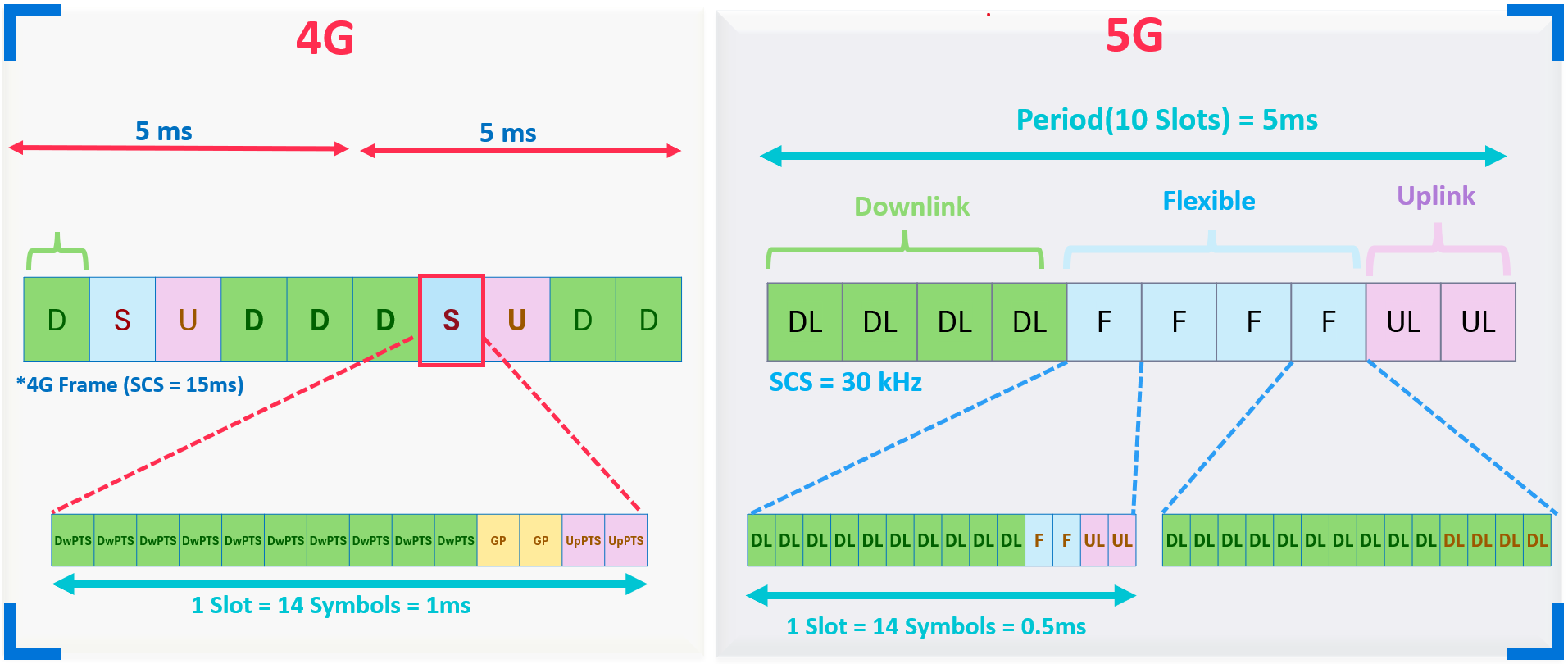
- The Special subframe (S) supports several patterns that can be controlled by a parameter called SSP (Special subframe pattern). Once the pattern is configured by the Operator/Vendor, the symbol allocation within the Special Subframe pattern(SSP) remains fixed without any changes and the primary configuration is outlined in Table 2 below, where the common used configuration in most of the network is SSP5 or SSP7.

As shown in the image below, the special subframe (S) in 4G has a fixed symbol allocation. In contrast, the special slot (F) in 5G can have either a fixed or dynamic allocation, managed by the gNodeB based on the services, as we will discuss later in this article."

(2) 5G Subframe and Slot Format Configuration
- 3GPP has specified the NR slot format to be very flexible. Individual slots and symbols can be configured as:
- Downlink, Uplink and Flexible

- Flexible symbols can be dynamically changed between uplink and downlink (they can include a Guard period for DL/UL Switching).
- RRC (SIB & UE dedicated signaling) and Physical Layer (PDCCH DCI) Signaling can be used to configure the slot format.
- There are 3 types of Slot assignment in NR TDD System:
- Static allocation: Means that the Flexible slot will have a fixed symbol configuration
- Semi-Static Allocation: Partially fixed flexible slot symbol allocation
- Dynamic Allocation: Dynamic means that the allocation of flexible symbols can be adjusted dynamically based on service and user requirements/demand, as illustrated in the image below.
NR Slot Format Types Deep dive
As highlighted earlier in this article, there are three types of slot assignments in the NR TDD system:
- Static allocation
- Semi-Static Allocation
- Dynamic Allocation
Now, let's delve deeper into each of them.
(1) Static allocation
- The name itself makes it clear that NR slot format static allocation is based on a fixed configuration defined by the operator/vendor. Sites will consistently use this configuration unless it is manually modified. The table below summarizes some of the possible combinations:

- As shown in the table above, there are two columns:
- Pattern (Column 1): This defines the overall structure of the slot configuration. For example,
DDDDDDDSUUindicates that the first 7 slots are fixed for downlink (DL), followed by one flexible slot. The flexible slot can have a combination of DL, uplink (UL), and guard symbols. - Flexible Slot Pattern (Column 2): This specifies the symbol allocation within the flexible slot (S-slot). For instance, a configuration of
6:4:4means that 6 symbols are allocated for DL, 4 for the guard band, and 4 for UL symbols.
- Pattern (Column 1): This defines the overall structure of the slot configuration. For example,

- The method for configuring the NR slot format described in the table above may vary between vendors. However, all implementations adhere to the 3GPP standard for the parameter structure, which defines a default uplink-downlink configuration for a cell. This structure can include one or two patterns as shown in the picture below, in addition to this the static allocation is configured to the UE through tdd-UL-DL-ConfigurationCommon.

- How to Verify Network NR Slot Format Settings from DT Logs?
- The above mentioned configuration and parameters are delivered to the UEs. Via SIB1 in 5G SA or RRC Reconfiguration in 5G NSA.
- Below is an example of an L3 message for the DDDDDDDSUU configuration:

(2) Semi-Static Allocation
- The Semi-Static allocation is mainly used by the gNB to partially refine the TDD slot format initially assigned to the UE. As shown in the image below, the gNB originally allocated a slot format of
DDDDDDFFFFFFFFFFUUUUto the UE through thetdd-UL-DL-ConfigurationCommonmessage. In this pattern, the flexible slots (denoted asF) remain unallocated in the center. These flexible slots are the only ones the gNB can modify, which is why they are referred to as "flexible slots." - Subsequently, the gNB sends a
tdd-UL-DL-ConfigurationDedicatedmessage to adjust the distribution of flexible slots in the configuration. As seen in the revised pattern, the first two flexible slots after the downlink slots are fully allocated to downlink symbols. This is followed by one slot that is partially allocated to downlink symbols. The remaining flexible slots in the center of the pattern remain unchanged. Further, one slot is partially allocated to uplink symbols, while the remaining slots are fully allocated to uplink. - The Semi-Static pattern, illustrated below, is the result of merging the
tdd-UL-DL-ConfigurationCommonandtdd-UL-DL-ConfigurationDedicatedconfigurations.

- The tdd-UL-DL-Configuration_Dedicated parameter structure shared in below picture can be provided to the UE using dedicated signaling.
- SlotIndex: Refers to the slot that will be modified.
- Symbols: Indicates the symbol allocation within the modified slot.
- This parameter structure can be used to refine the UL/UL transmission pattern provided by tdd-UL-DL-Configuration_Commonaaa

(3) TDD Dynamic Slot Allocation
- The Dynamic TDD slot allocation is a key advantage introduced in 5G compared to 4G.
- It allows the gNB to dynamically adjust the flexible slots that remain unallocated in static or semi-static configurations.
- For example, if the gNB detects that the user is engaged in heavy downlink transmission, it can assign more downlink symbols within the flexible slots.
- Similarly, if the user is performing heavy uplink transmission, the gNB can dynamically reconfigure the allocation to assign more uplink symbols within the flexible slots.
- In general, the gNB's allocation follows the standard 3GPP table, which provides 56 predefined combinations.
- As shown in the two pictures below, the first image illustrates that the flexible (F) slots can be dynamically adjusted by the gNB, following the 3GPP table provided below. The second image demonstrates various scenarios for symbol allocation based on different services.


Important Notes:
- The following are the key parameters used by the gNB to instruct the UE on the configuration changes.
- The UE monitors the PDCCH for UL & DL resource allocations during any Flexible symbols/Slots that have been configured using semi-static parameters structure.
- However, the UE does not monitor the PDCCH for resource allocations during any Flexible symbols/slots that been configured using DCI Format 2_0.
- The Flexible Slots can be used to generate reserved periods during which the UE does not transmit nor receive. i.e: can be used during 4G/5G Spectrum sharing

- Below are all the 3GPP slot combinations that can be used for Dynamic TDD.

Before moving to the next topic, I want to highlight an important point regarding TDD dynamic allocation. Typically, TDD dynamic allocation should be used in very specific scenarios to avoid cross-link interference. Imagine a network where neighboring cells are assigned different patterns of symbols and slots—this could lead to significant interference between downlink and uplink transmissions, referred to as cross-link interference, as shown in the picture below. For this reason, the use of TDD dynamic allocation will likely be limited to specific scenarios in the future.
Cross Link Interference(Due to Dynamic Allocation)

(4) 4G/NR coexistence
- 4G and NR co-existence refers to scenarios where 4G TDD and 5G TDD bands share the same frequency. For example, in networks with mixed 4G TDD and 5G TDD sites, where the 4G TDD band has not yet been fully migrated to 5G, operators and vendors must carefully ensure that the slot and symbol allocations completely overlap to avoid interference between downlink (DL) and uplink (UL) slot allocations.
- As shown in the image below, the 4G network is configured with a 4:1 subframe configuration, using a 15 kHz subcarrier spacing (SCS). To achieve full overlap between 4G and NR, two scenarios can be implemented:
- Scenario 1: Use the NR TDD UL-DL pattern 4:2:4 with zero frame offset (starting point).
- Scenario 2: Use the TDD UL-DL pattern 8:2 with a frame offset of 3 ms.


(5) NR Slot Format Planning and design impact on the KPIs Performance
- The NR slot format design can impact throughput, coverage, latency, and RACH planning, as illustrated in the image below. For more details, you can refer to the video linked below.

The following videos covers the same in more details:
Interesting Materials for the same added below:

Sources:
- 5G NR in Bullets
- The New generation wireless access technology
- 3GPP TS 36.211
- 3GPP TS 38.213


