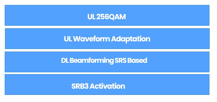
Key 5G RAN Features: DL Beamforming, UL 256QAM, Waveforms & SRB3 Activation- Article

Content:
- This article simplifies the basic understanding of 4 features and explains how to verify features functionalities from the traces and field testing. The same content was already explained earlier in a YouTube video (shared below)
(1) UL 256QAM
Expected gain
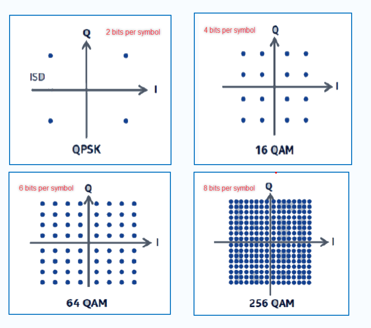
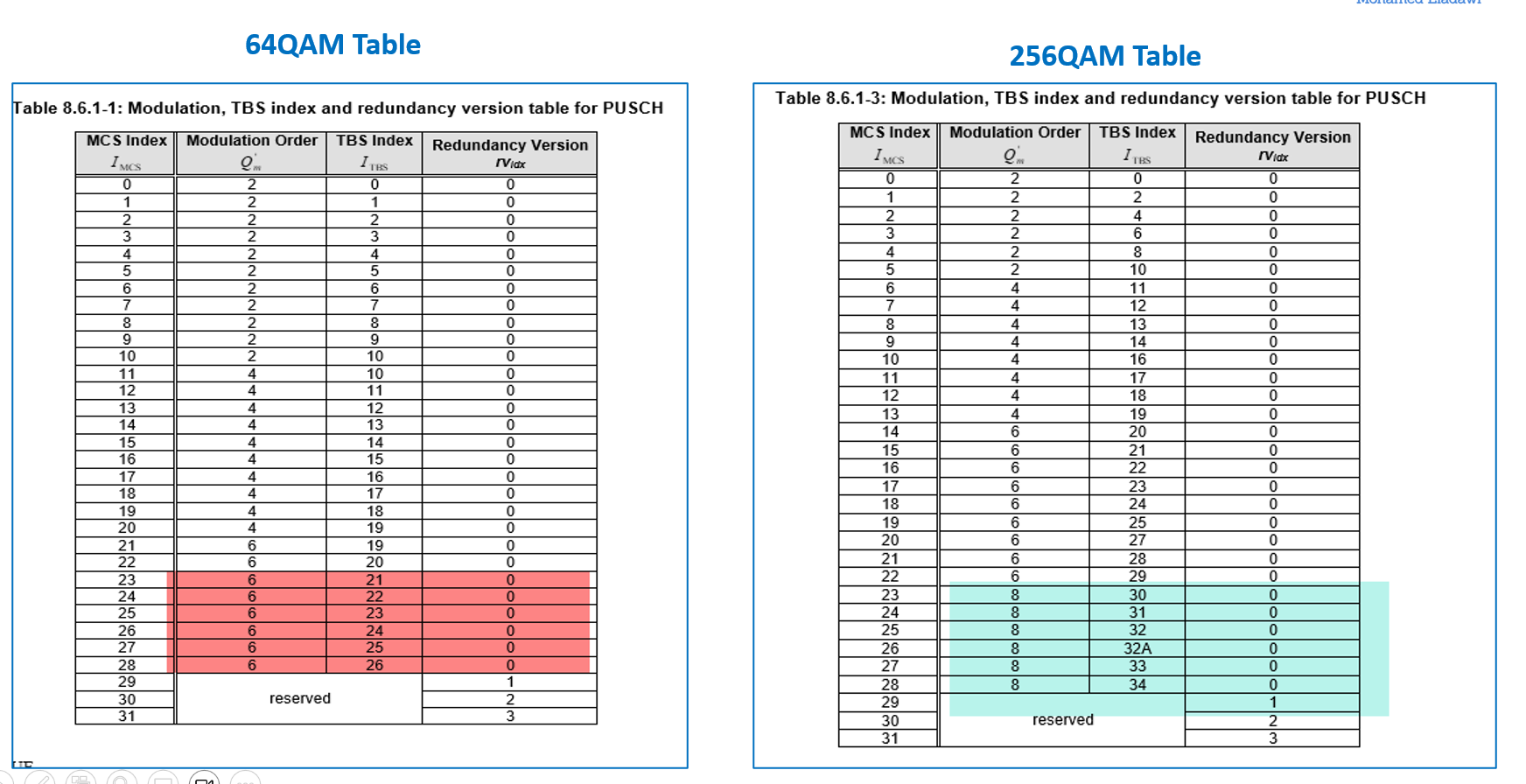
- UL 256QAM is a basic feature in 5G. UL 256QAM provides around 33% gain in 5G UL Peak speed compared with 64QM, as UL256QAM transfer 8 bits per symbol while 64QAM transfer 6 bits per symbol.
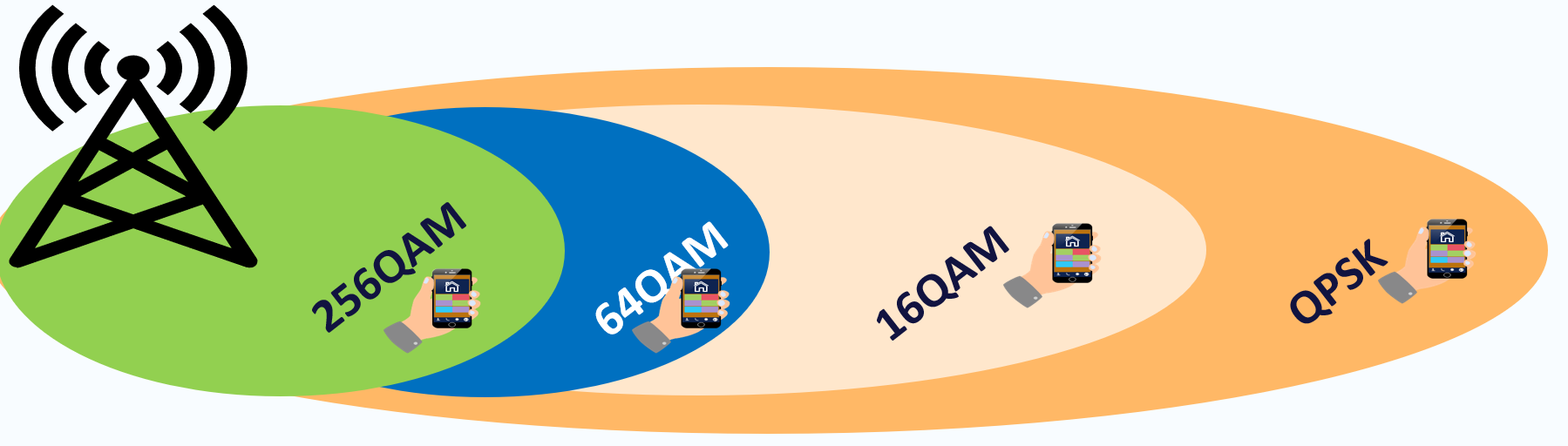
- Under favorable radio environments where users are near the cell center and are enjoying a very good SINR, Peak UL User throughput using 256QAM can increase up to 33% compared to 64QAM.
Verification Steps for Field Testing Features:
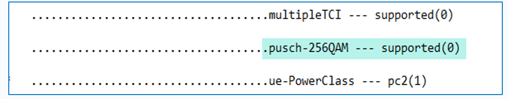
- Confirm UE Capability – 256QAM support
- Before starting field testing, confirm that the test device supports UL 256 from the below-given message, which can be checked through the UE Capability message.
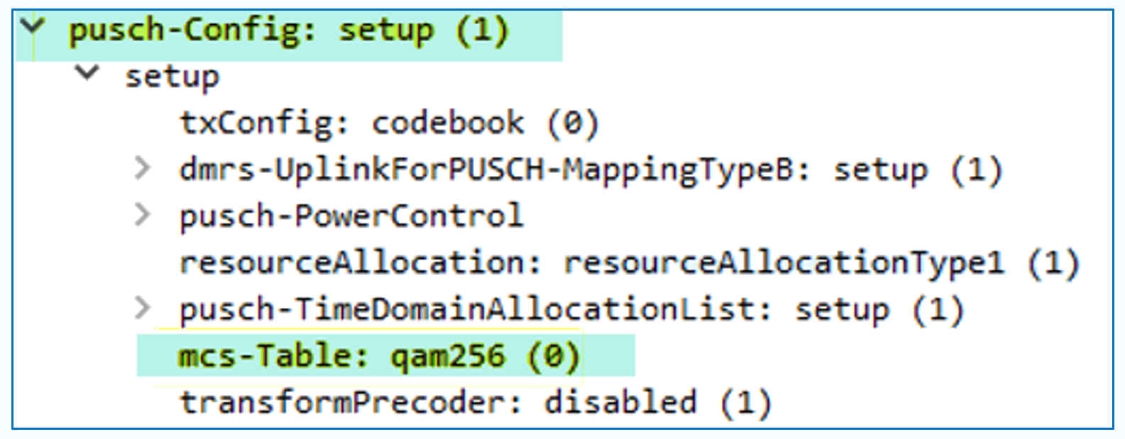
- After starting the test, you need to check and confirm that MCS-Table: 256qam is delivered in RRC Reconfiguration msg to the test UE.
The below is a 3GPP comparison tables between 256QAM & 64QAM for reference:
(2) PUSCH Waveform Adaptation
Introduction
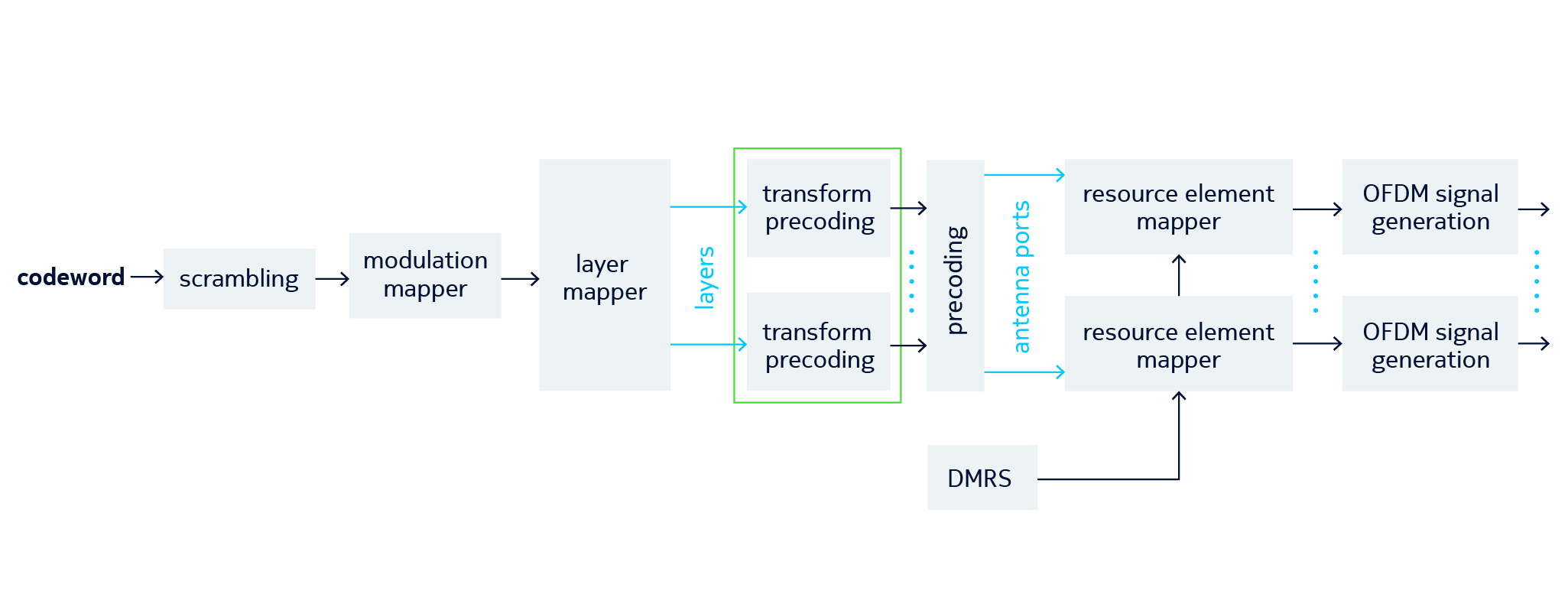
- The waveform is the baseband signal which is mixed to RF before being radiated across the air interface.
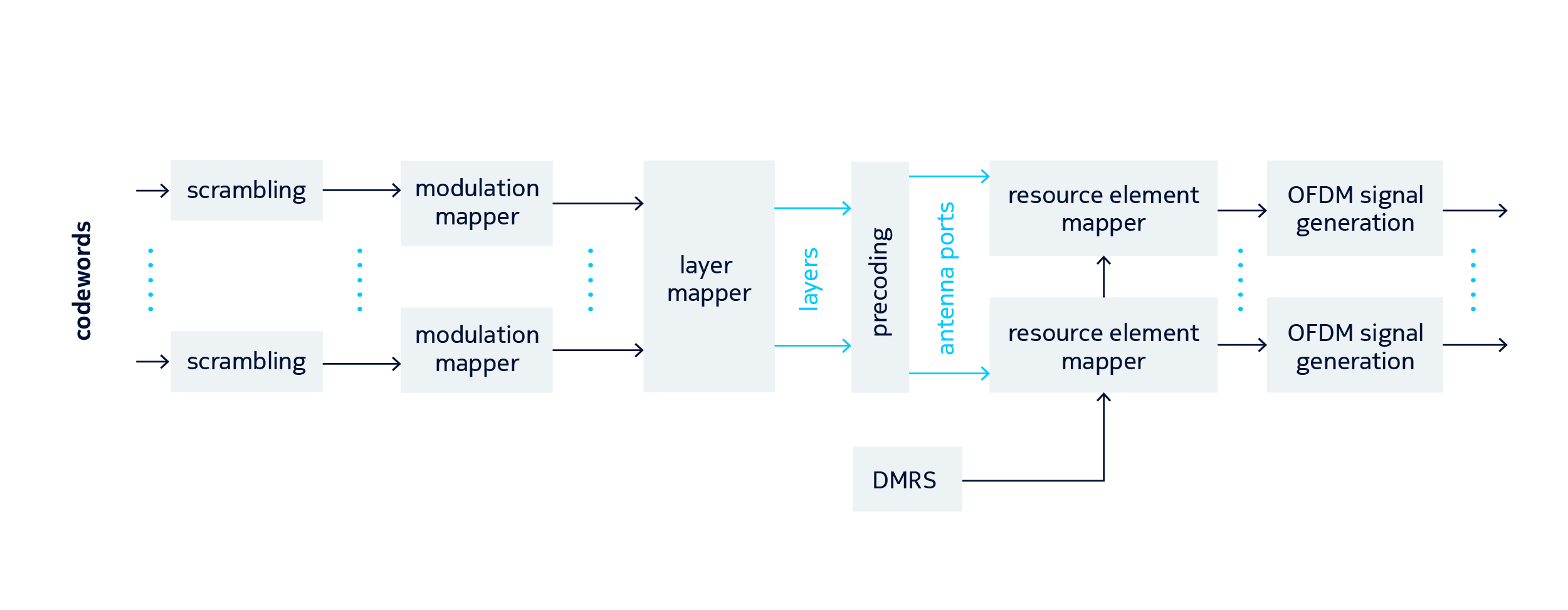
- 3GPP has specified two waveforms for New Radio(NR) based upon Orthogonal Frequency Division Multiplexing(OFDM):
- Cyclic Prefix-Orthogonal Frequency Division Multiplexing (CP-OFDM), Applicable to both UL & DL
- Discrete Fourier Transform Spread OFDM ( DFT-S-OFDM), applicable to UL only:
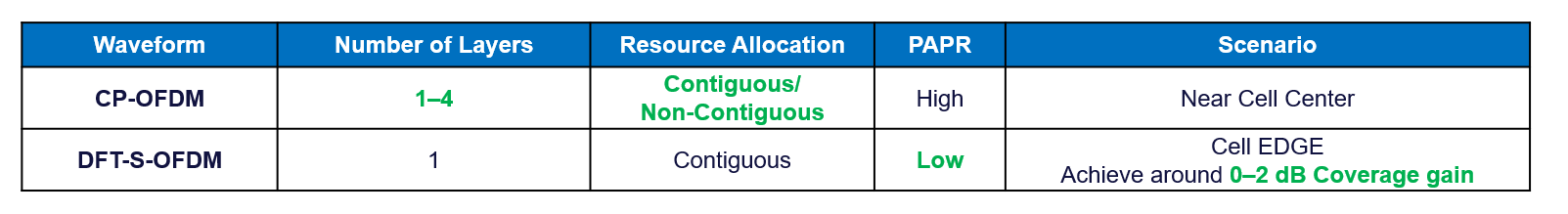
The following summarizes the differences between CP-OFDM and DFT-S-OFDM
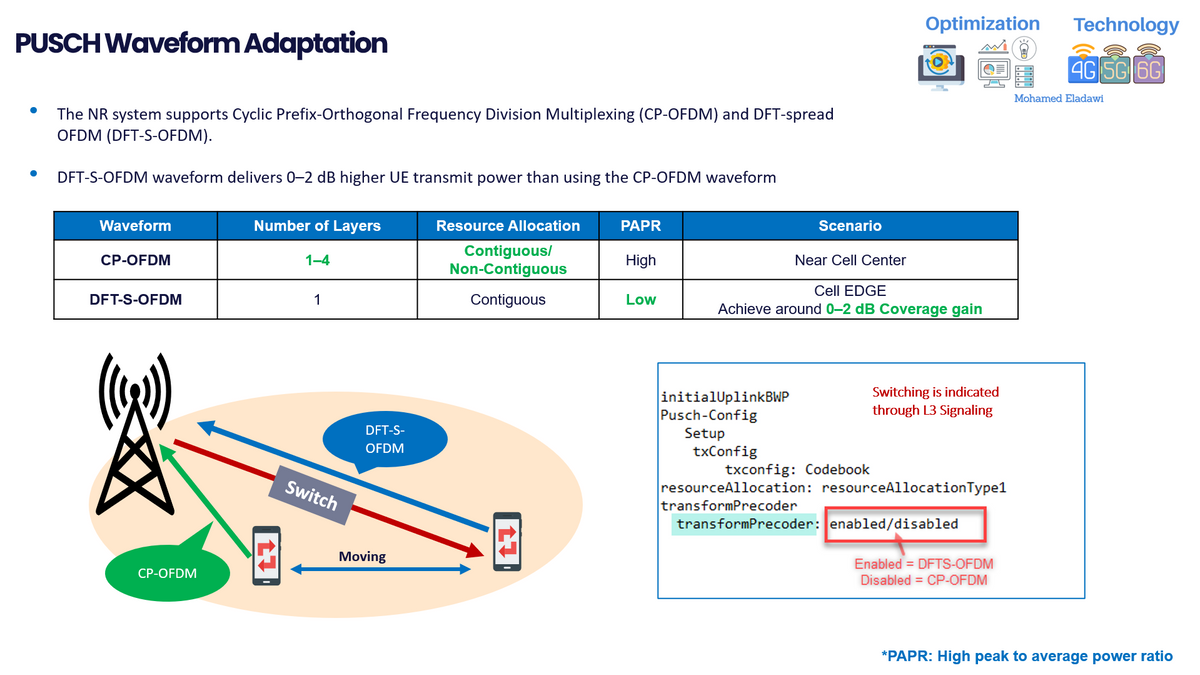
- CP-OFDM is characterized by flexible resource allocation. However, this allocation of resources can produce a high peak-to-average power ratio (PAPR).
- DFT-S-OFDM requires contiguous frequency-domain resources and ensures low PAPR and high transmit power.
- Using the DFT-S-OFDM waveform delivers 0–2 dB higher UE transmit power than using the CP-OFDM waveform.
- 3GPP has specified that DFT-S-OFDM only supports single stream transmission.
- In general, CP-OFDM offers improved throughput and capacity in good radio conditions, while DFT-S OFDM offers improved coverage at the cell edge.
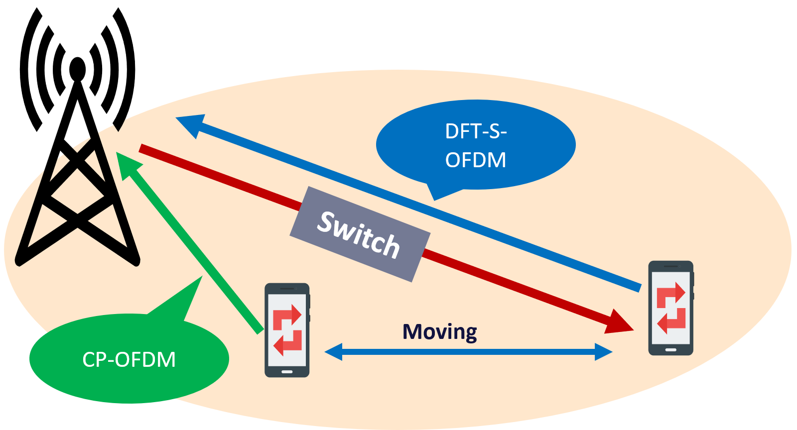
How PUSCH Waveform Adaptation works?
- The BTS may dynamically reconfigure the UE according to the coverage conditions.
- Usually, BTS relies upon a pre-defined threshold for PUSCH SINR to switch between both waveforms.
- As shown in the below-given figure, BTS switched to DFT-S OFDM once the user moved to Cell Edge.
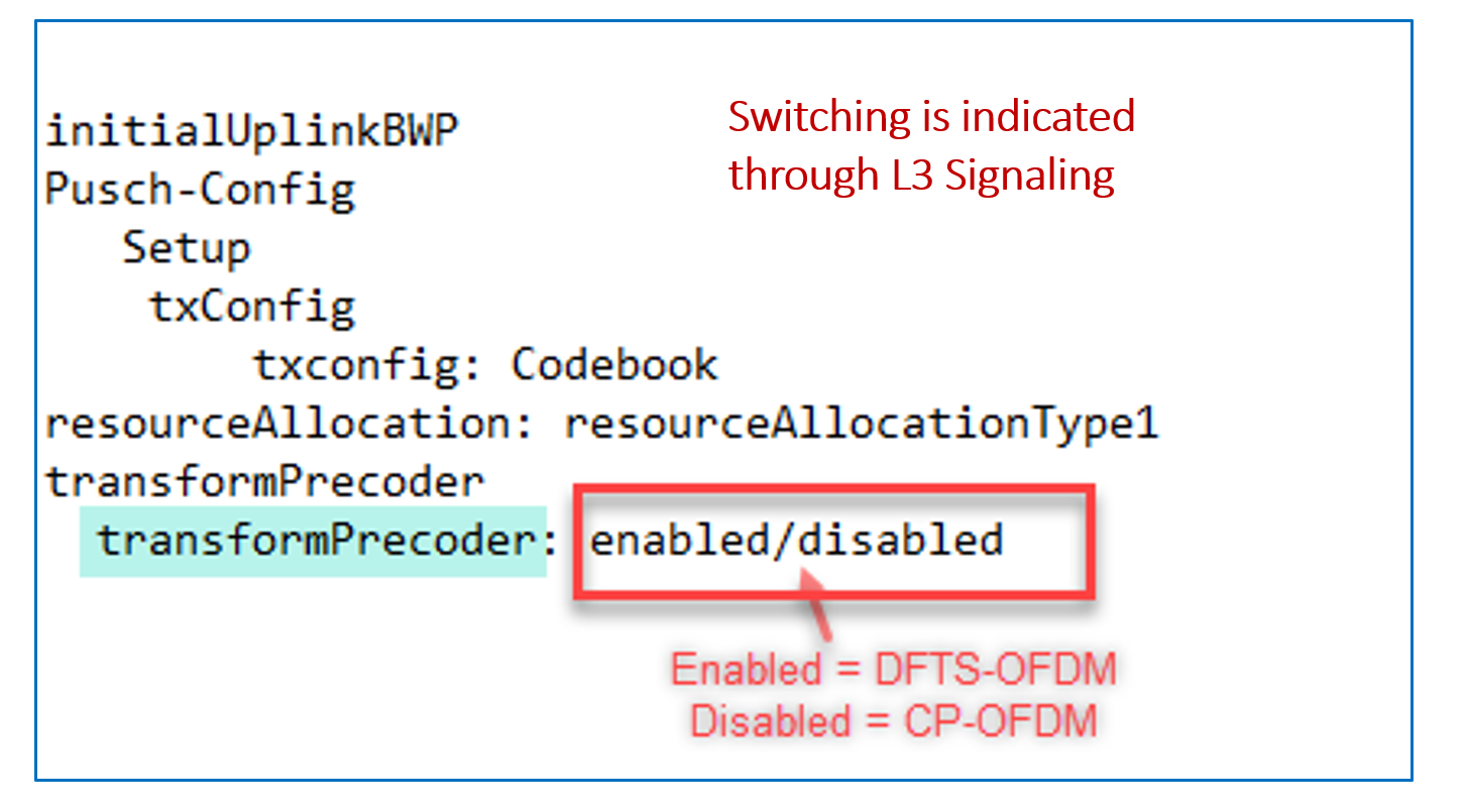
- The BTS instructs the UE to switch or use a specific mode by sending RRC reconfiguration message, where you need to check the transform precoder value under Pusch-Config message.
💡
After the uplink waveform adaptation function is enabled, some devices compatibility issues may occur on UEs not supporting the DFT-S-OFDM waveform, causing service drops. however this was being observed at the very initial stage of the 5G Deployment
(3) DL Beamforming weight calculation based on SRS feedback
Introduction:
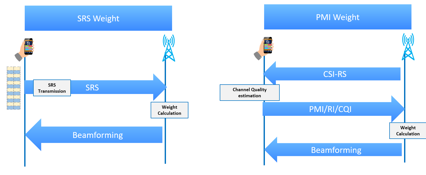
- Generally, BTS Adjusts the shape and direction of downlink beams, and the BTS calculates the weight based on the UE feedback for the DL Channel Characteristics.
- DL Beamforming weight calculation is measured by the BTS after receiving the feedback UE, two different methods can be used by the Users to provide feedback.
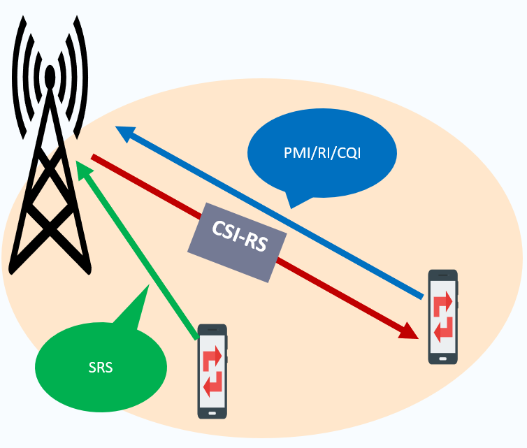
- Through measuring CSI-RS “Codebook-based transmission.
- Through transmitting SRS, “Reciprocity-based transmission.”
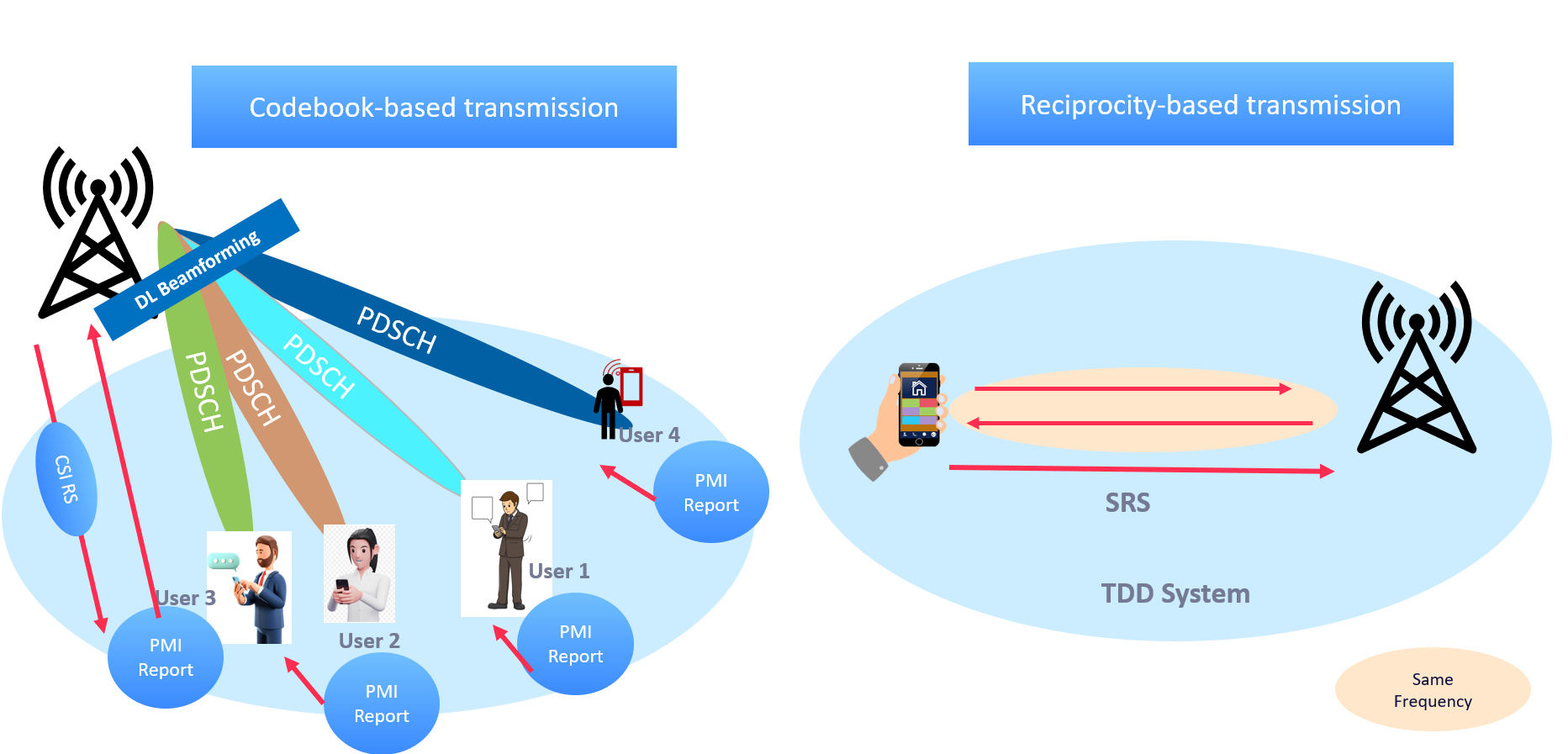
- The main differences between both methods are that:
- SRS Provides better gain, especially in good radio condition, as the BTS will timely measure the channel propagation and find the best beam more quickly.
- CSI-RSI "PMI Weight" can provide more accurate measurement in the Cell Edge where the SRS Coverage is poor and there is an imbalance between DL/UL coverage.
- The BTS can switch between both modes based on pre-defined thresholds for SRS SINR.
SRS DL-Based Beamforming ”Test Verification”
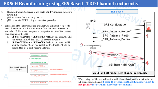
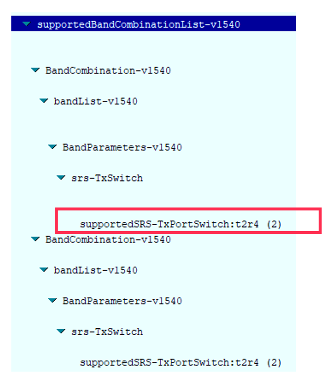
BTS can use SRS to estimate the downlink propagation if the UE supports any of the following categories:
- The number of transmit paths at the UE equal the number of receive antenna at the UE; in this case, the SRS can be transmitted from each UE receive antenna so the Base Station can deduce the Downlink propagation channel towards each antenna
- The number of transmit paths at the UE is less than the number of receive antennae at the UE; in this case, the UE must be capable of antenna switching to allow the SRS to be transmitted from each receive antenna. UE declares this capability to the Base Station to allow the SRS to be configured appropriately.
The below highlighted parameter " supportedSRS-TXPortSwitch if not included in the UE capability message this means the device does not support
To Confirm the current SRS Usage, you can check the below-highlighted message in the RRC reconfiguration message. USAGE= Antenna switching indicates that the SRS will be used for DL estimation purpose

SRB3 Activation
Introduction
- SRB3 is optional and provides a direct SRB between the Secondary RAN Node and the device as shown below.
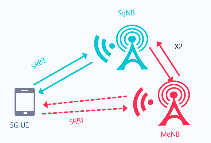
- The following RRC messages will be handled through SRB3 For EN-DC operation:
- RRC Reconfiguration.
- RRC Reconfiguration Complete.
- Measurement Report.
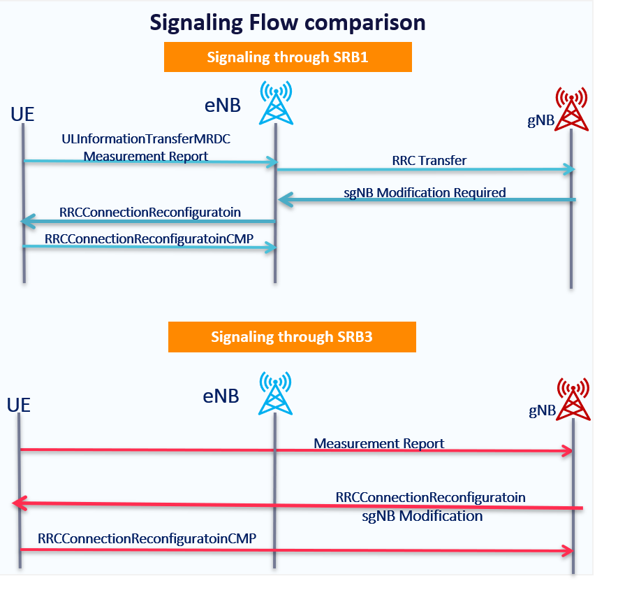
Expected Benefit:
- RRC Signaling through using NR SRB3 might reduce the latency.
💡
If the UE does not support SRB3, signaling cannot be directly exchanged between the gNodeB and the UE
YouTube video for the same
Sources:
- Section 7.5 "SRB3" in 3GPP TS 37.340 V15.7.0
- 5G NR in Bullets