The Basics of 5G DL DMRS(With Video)


This article covers the key aspects of the 5G Downlink Demodulation Reference Signal (DL DMRS). The following topics will be discussed:
- DMRS for PDCCH Function
- DMRS for PBCH Function
- DMRS for PDSCH Function
- Walk through DMRS parameters for PDSCH
- Configuration Type 1 and Type 2: Impact frequency domain allocation
- PDSCH Mapping types A and B.: Impact time domain allocation
- DMRS FOR PDSCH Additional Position: Good for high speed UEs
(1) DMRS for PBCH
What is the main function of DMRS for PBCH?
- The UE uses DMRS to estimate the propagation channel experience by the PBCH.
- The resultant information is used to demodulate the PBCH and subsequently decode the Master Information Block.
How and where is it being transmitted?
- The DMRS for the PBCH is transmitted by the Base Station using antenna port 4000.
- PBCH is transmitted within SSB Block in Symbols 1, 2, and 3, as shown below.
- There are no Resource Elements for the DMRS within the first symbol, as the PBCH does not use this symbol.
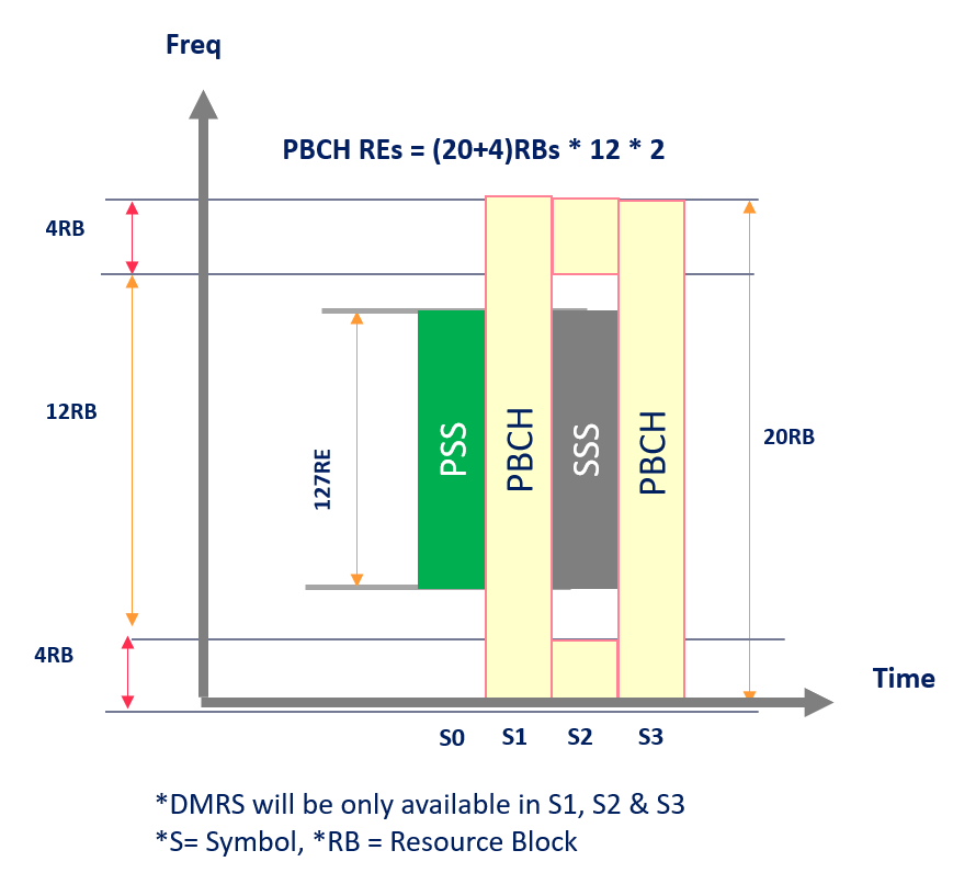
Where is it being allocated within S1, S2, and S3, and what overhead is added by DMRS for PBCH?
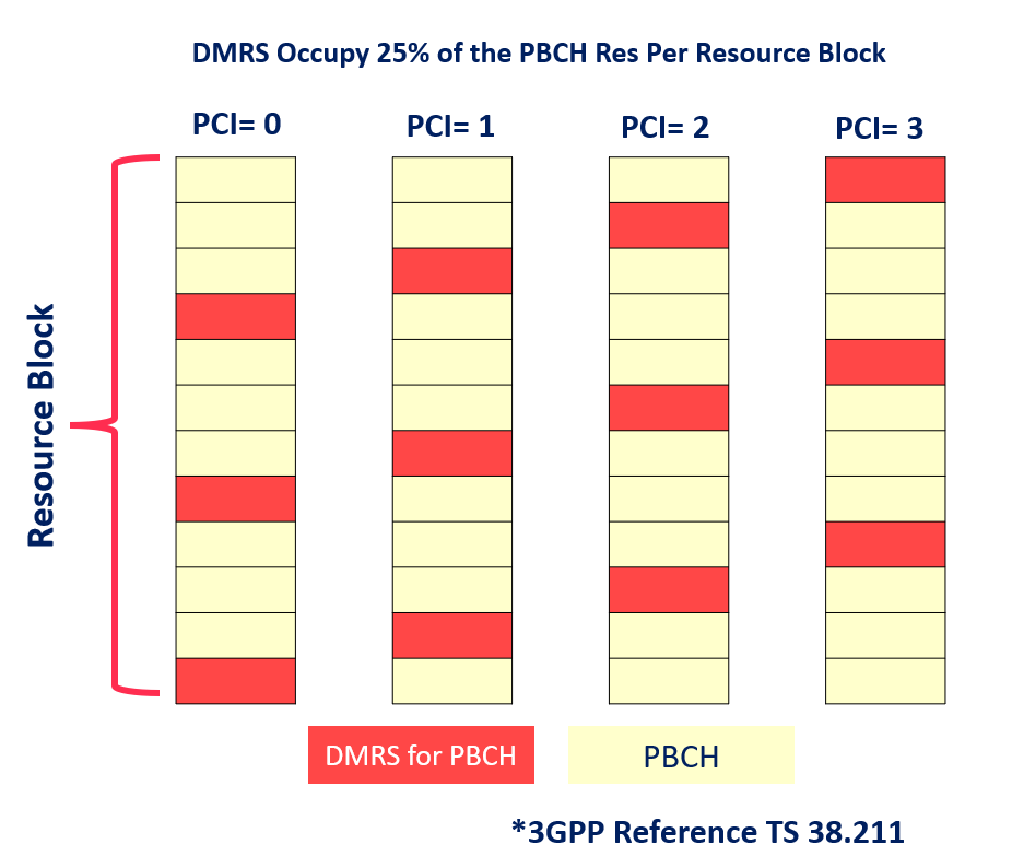
- The DMRS is allocated to every 4th Resource element and is designed based on PCI mod 4.
- DMRS Occupy 25% of the PBCH Res Per Resource Block,
- Where S1/S3 = 20RB * 3 DMRS RE = 60RE, and S2= 8RB * 3 DMRS RE = 24RE
💡
RB: Resource Block, RE: Resource elements
(2) DMRS for PDCCH
What is the main function of DMRS for PDCCH?
- The UE uses DMRS to estimate the propagation channel experience by the PDCCH.
- The resultant information is used to demodulate the PDCCH and subsequently decode the Downlink Control Information ( DCI).
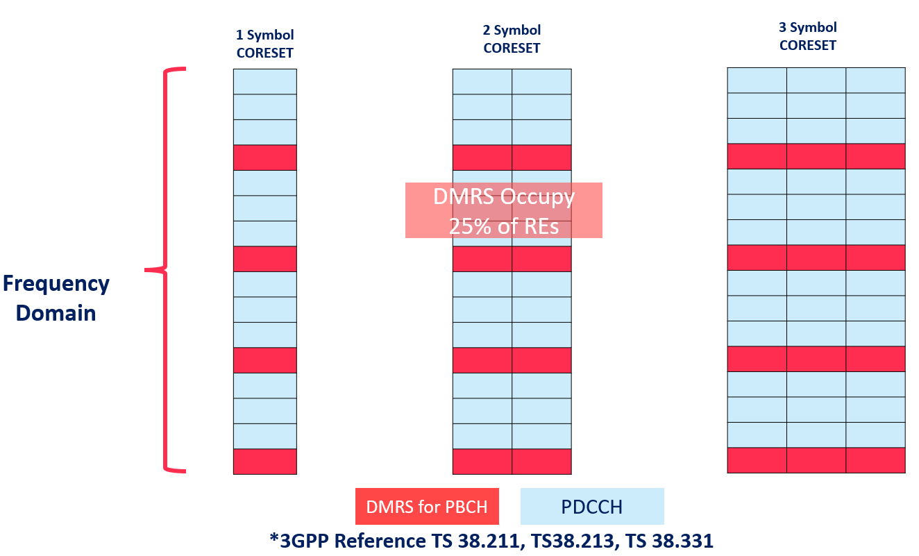
- The PDCCH DMRS Resource elements are located in a fixed location. (1,5, 9, 13, 17, 21, ….)
- DMRS for PDCCH Occupy 25% of REs
(3) DMRS for PDSCH
What is the main function of DMRS for PDSCH?
- The UE uses DMRS to estimate the propagation channel experienced by the PDSCH.
- PDSCH is always transmitted in combination with DMRS, and both use the same antenna ports(1000 to 1011)
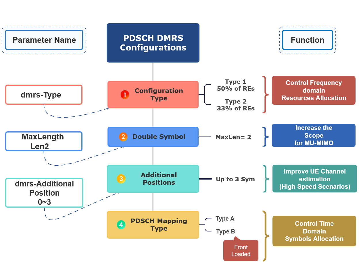
- PDSCH DMRS Configurations depend upon the below-mentioned variables, and these configurations account for Requirements associated with both SU-MIMO and MU-MIMO
- DMRS is used to estimate the radio channel. The signal is present only in the RBs allocated for the PDSCH.
What are the parameters that control time-domain resources for DMRS PDSCH?
- PDSCH symbol allocation
- Mapping type
- DMRS type A position
- DMRS length
- DMRS additional position
💡
The mentioned parameters will be covered in more detail in this article.
In General, The DMRS for the PDSCH structure is designed to support different deployment scenarios and use cases.
- A front-loaded design supports low-latency transmissions.
- The front-loaded reference signals indicate that the signal occurs early in the transmission. The DM-RS is present in each RB allocated for PDSCH.
- Twelve orthogonal antenna ports for MIMO transmissions.
- Up to four reference signal transmission instances in a slot to support high-speed scenarios.
(4) Walk through DMRS parameters for PDSCH
(A) DMRS FOR PDSCH: Configuration Types
- There are two types of configuration of DMRS for PDSCH
- (Type 1 and Type 2)
- The Configuration Type impacts the frequency domain resources used by the DMRS.
DMRS for PDSCH Configuration Type 1:
- There are two types of configuration type1 (Single Symbol and Double Symbol)
- As shown below configuration Type1 is allocated every 2nd Resource Element to the DMRS.
- This increases the DMRS Density, and the Higher the density increases the overhead, and in the case of MU-MIMO, it reduces the scope for frequency multiplexing with the DMRS belonging to other UE.
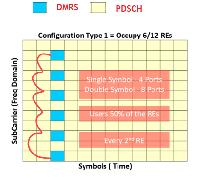
For Configuration Type 1 (Single Symbol)
- The higher density of REs used by Config Type 1 helps the UE to generate a more accurate Channel estimate.
- This makes Configuration Type 1 suitable for transmissions requiring high reliability or UE experiencing poor coverage.
- The higher density generates an increased overhead, and in the case of Multi-User MIMO, it reduces the scope for frequency multiplexing with the DMRS belonging to other UE.
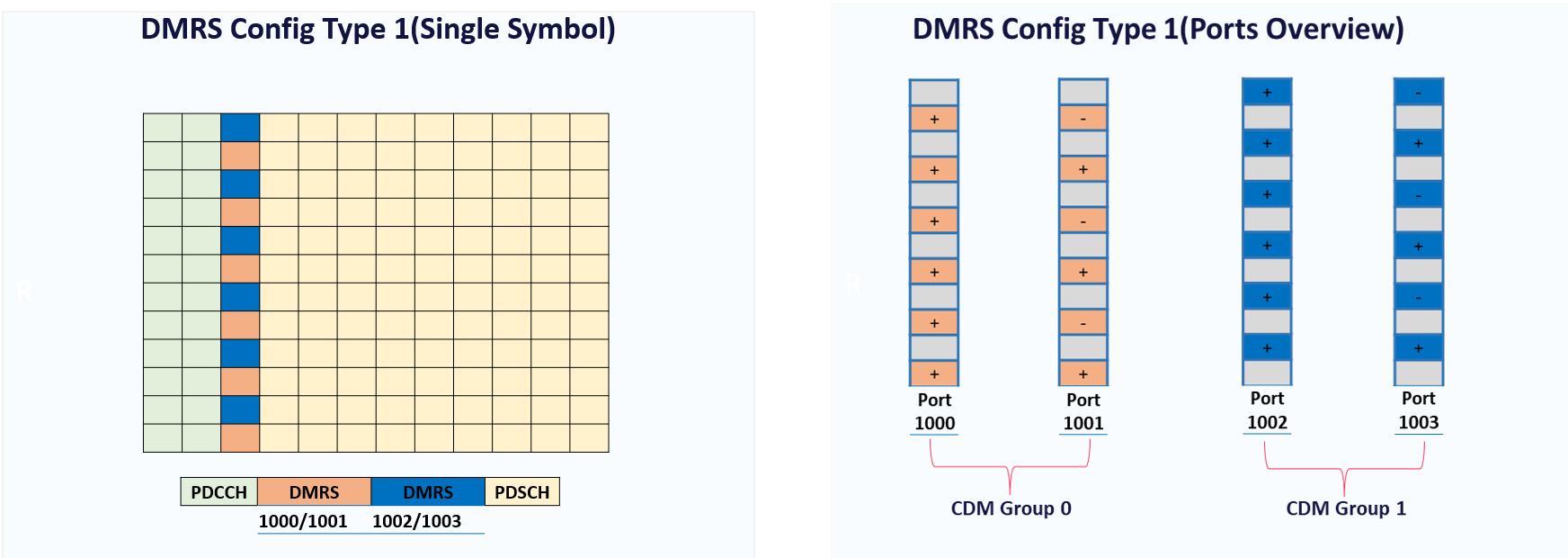
- Single Symbol transmission with Configuration Type 1 supports 4 antenna ports so that it can support up to 4x4 MIMO. (See below picture)
- If a UE receives 4 layers of data (rank 4) with Single User MIMO, antenna ports 1000 to 1003. These 4 antenna ports fully occupy the DMRS symbol, and no Resource Elements are available for the PDSCH.
- If a UE receives 1 layer of data (rank 1) with Single User MIMO can be allocated antenna port 1000. This antenna port occupies only half of the Resource Elements within the DMRS symbol.
- A UE receiving 2 data layers (rank 2) with Single User MIMO can be allocated antenna ports 1000 and 1001. This pair of antenna ports occupies only half of the Resource Elements within the DMRS symbol. In both cases, the remaining Resource Elements can be used by the PDSCH.
💡
In the case of Multi-User MIMO, a first UE could be allocated single-layer transmission with port 1000, while a second UE is allocated single-layer transmission with port 1001, and a third UE is allocated single-layer transmission with port 1002.
For Configuration Type 1 (Double Symbol)
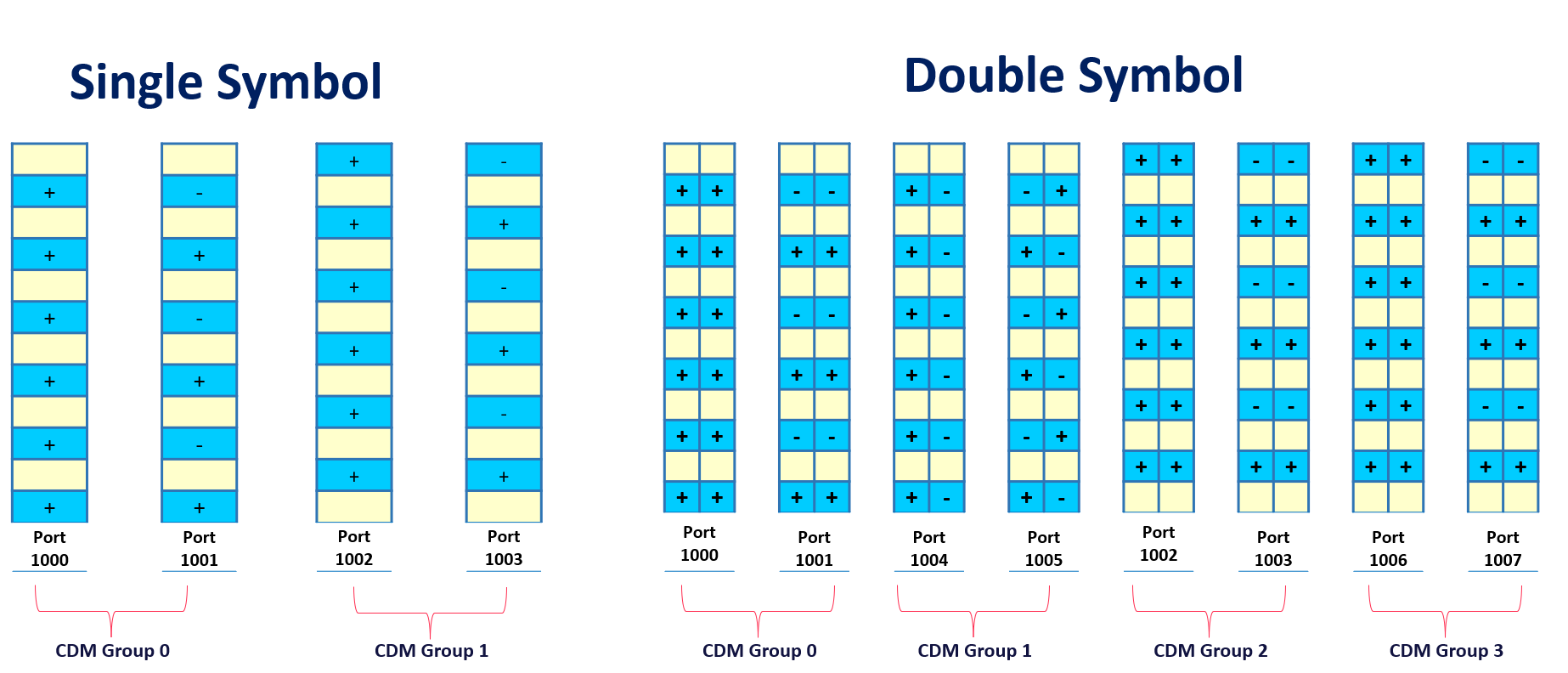
- Using a pair of symbols increases the code multiplexing capability of the DMRS, i.e., there are 4 antenna ports per CDM group rather than 2 antenna ports per CDM group.
- This increases the total number of antenna ports and so increases the scope for Multi-User MIMO.
💡
More Antenna Ports = Higher Scope for MU-MIMO
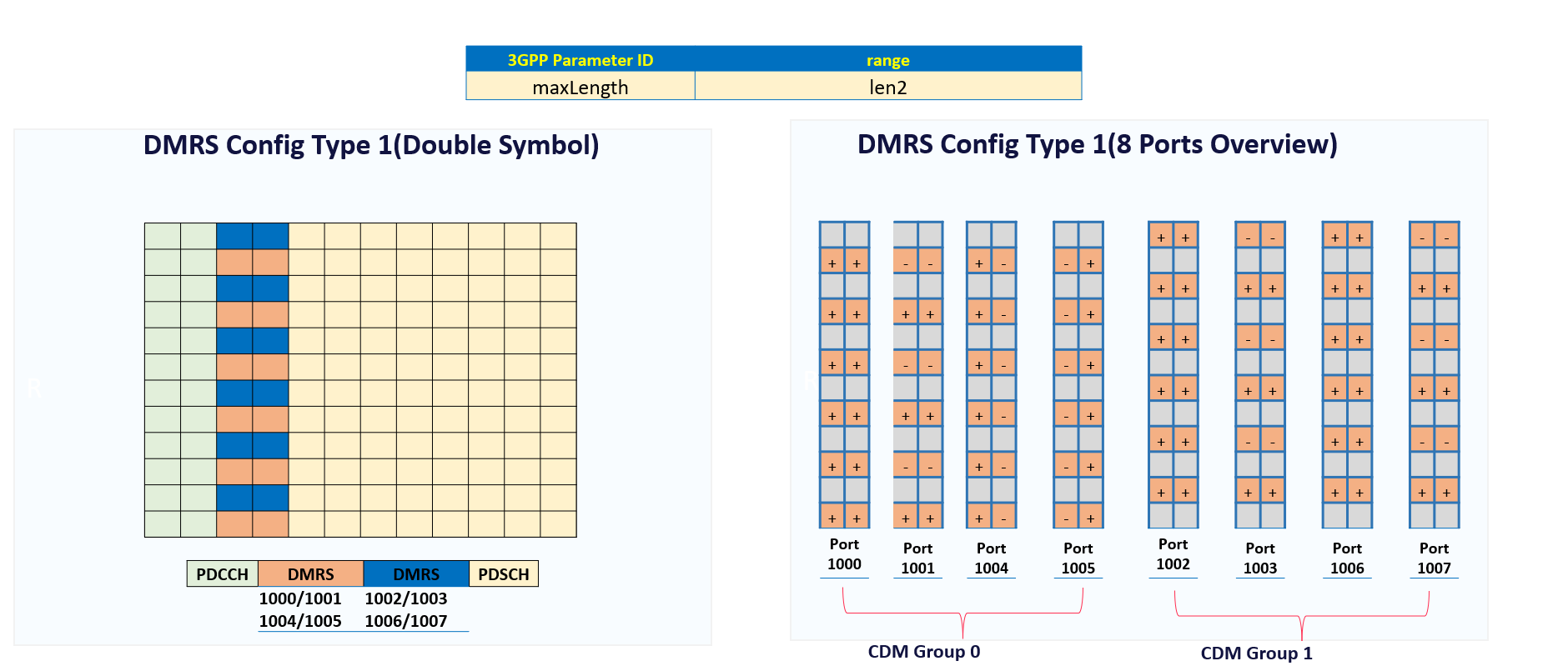
- As shown below pictures, increasing the number of symbols increases the number of ports for Configuration Type 1 (Single Symbol) from 4 Ports to 8 Ports (Double Symbol)
DMRS for PDSCH Configuration Type 2:
- As shown below configuration Type2 is allocated every third pair of Resource Element to the DMRS.
- This increases the scope for frequency multiplexing and accordingly increase the Scope of MU-MIMO.
- Configuration Type 2 uses 33 % of the Resource Elements within the symbols allocated to the DMRS.
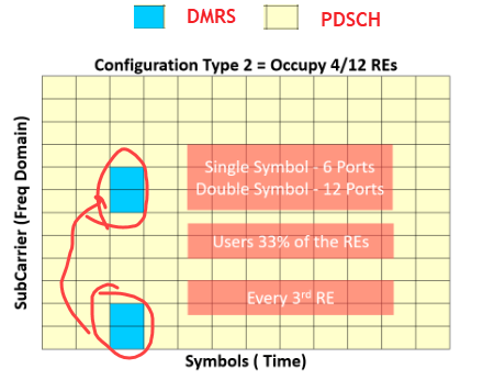
- There are two types of configuration type1 (Single Symbol and Double Symbol)
- DMRS Type 2, both single and double symbols, follow the same concept as explained for DMRS Type 1.
(B) DMRS for PDSCH Mapping Type
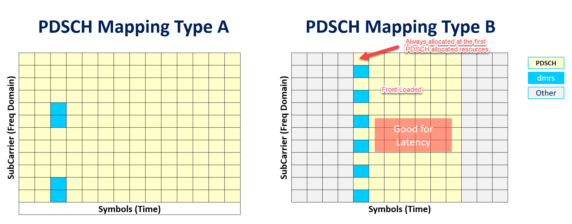
- DMRS for PDSCH has two types of PDSCH Mapping, PDSCH Mapping Types A and B.
- The PDSCH Mapping Type has an impact upon the time domain symbols allocated to the PDSCH. This impacts the symbols allocated to the DMRS because the DMRS can only use a subset of the resources allocated to the PDSCH.
- PDSCH Mapping Type A: is sometimes referred to as providing ‘Slot’ based scheduling’.
- In PDSCH Type A, first DMRS is located in Symbol 2 or 3 of the slot
- PDSCH Mapping Type B: is sometimes referred to as providing ‘Non-Slot’ based Scheduling or ‘Mini Slot' based scheduling’ (Mapping Type B is restricted to allocating up to 7 symbols)
- PDSCH Type B is always located at the first Symbol of PDSCH Allocation. (Called Front Loaded ).
- A front-loaded design supports low-latency transmissions.
- The front-loaded reference signals indicate that the signal occurs early in the transmission. The DMRS is present in each RB allocated for PDSCH.
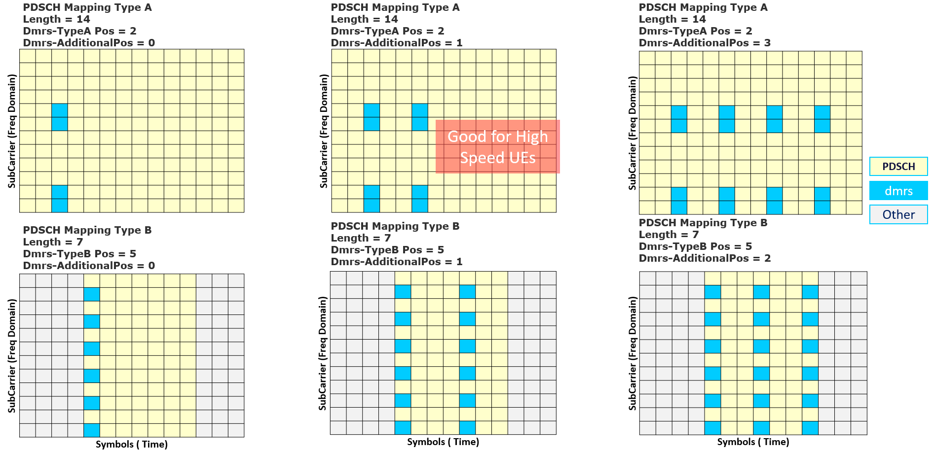
(C) DMRS FOR PDSCH Additional Position
- Mapping Types A and B both allow the DMRS to use additional symbols.
- Additional DMRS symbols can help to improve the UE channel estimation performance.
- If a PDSCH transmission includes 2 DMRS symbols, the propagation channel can be measured at 2-time instants(as shown in below picture) and then interpolated between those time instants.
- Increasing the number of DMRS symbols reduces the gap between channel estimates and reduces the requirement for long interpolations.
- This is particularly important for high-speed scenarios where the propagation channel can change rapidly and there are large frequency offsets to track.
💡
The drawback of additional DMRS symbols is an increased overhead.
💡
The requirement for additional DMRS symbols can depend upon the subcarrier spacing because higher subcarrier spacings have shorter symbols, which allows less time for the propagation channel to change, i.e., higher subcarrier spacings require fewer additional DMRS symbols.
For example, 4 DMRS symbols may be required to achieve good performance for very high-speed scenarios when using a 30 kHz subcarrier spacing, while 3 DMRS symbols may be sufficient for the same scenario when using the 60 kHz subcarrier spacing.
For example, 4 DMRS symbols may be required to achieve good performance for very high-speed scenarios when using a 30 kHz subcarrier spacing, while 3 DMRS symbols may be sufficient for the same scenario when using the 60 kHz subcarrier spacing.
Video for the same
Sources:
- 5G NR in Bullets


