5G CSI-RS Deep Dive (Article + Video)

Introduction:
This Article will cover most of the related aspects and details about the 5G Channel State Information Reference Signal ( CSI-RS)
The following will be substituted in this article
- What are CSI-RS's Main Functions?
- CSI-RS Key Characteristic.
- CSI-RS Types & Categories.(NZP, ZP & CSI IM)
- CSI-RS Basic Structure.
- CSI-RS Main Parameters ”Layer 3 messages”
- CSI-RS UE Capability Check.
- Frequency & Time Domain Structure of CSI-RS Configurations.
- CSI Reference Signal Planning.
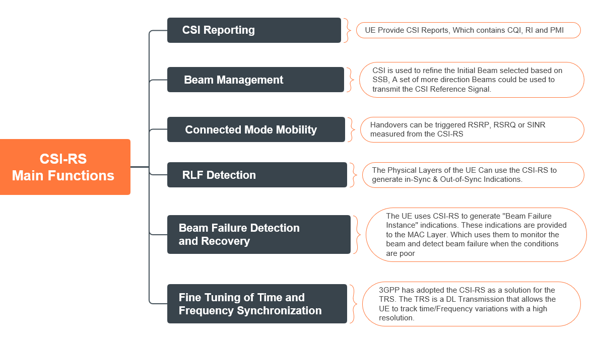
(1) What are CSI-RS's Main Functions?
- The Channel State information (CSI) Reference Signal is a multi-purpose DL Transmission.
- The Base Station can configure the UE to use the CSI-RS for one or more of the following:
💡
Some procedures, like Connected Mode Mobility, RLF detection, and Beam Failure detection, can also use SS/PBCH Block measurements.
💡
The listed procedures use "Non-Zero Power CSI Reference Signals" for channel measurement, configured via dedicated signaling, which will be detailed in this article.
Now let's try to simplify CSI-RS Main functions.
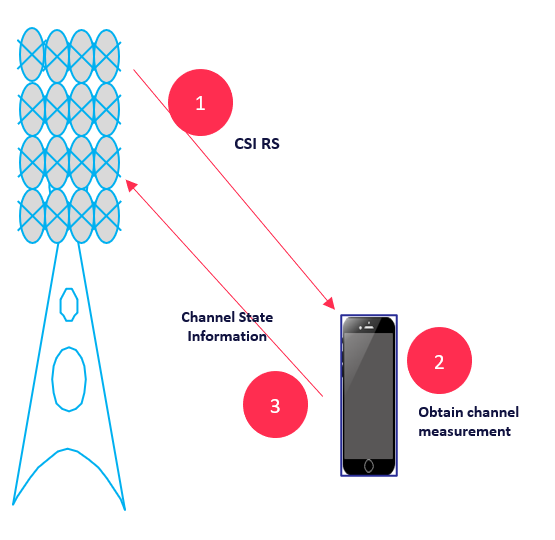
1- CSI Reporting
- As seen in the below figure, the g-NB initially will send the related configuration and transmit CSI RS in the Downlink; then the UE will decode the corresponding CSI RS to obtain channel measurement after the UE reports the so-called Channel start information(CSI)
- The UE reports Channel State Information (CSI) to the Base Station using either the PUSCH or the PUCCH; the Base Station uses the CSI to support its downlink transmissions on the PDSCH and PDCCH and CSI report Includes the following:
- Channel Quality Indicator (CQI)
- CSI-RS Resource Indicator
- Rank Indicator
- Layer Indication (LI)
- Precoding Matrix Indicator( PMI)
- L1-RSRP
- SS/PBCH Block Resource Indicator (SSBRI)
2- Beam Management “Refinement.”
- Once a UE has entered RRC Connected mode, it is possible to initiate Beam Refinement procedures.
- These procedures can select more directional beams with higher gain. More directional beams can improve the link budget.
- The CSI Reference Signal can be used to support Beam Refinement procedures.
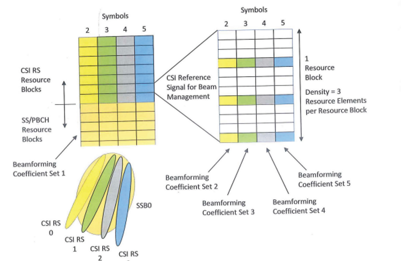
- For example, As shown in the below figure, a set of 4 CSI Reference Signal resources can be associated with each SS/PBCH Block
- a Total of 32 CSI Reference Signal resources would be configured using the maximum of 8 SS/PBCH Blocks in Frequency Range 1.
- The Base Station can apply different beamforming coefficients to each CSI Reference Signal resource to generate 4 directional beams per SS/PBCH Block.
- Each set of 4 CSI Reference Signals can be time multiplexed across four symbols and frequency multiplexed with the associate SS/PBCH Block.
- The below figure illustrates a set of 4 CSI Reference Signals that use the Resource Blocks above an SS/PBCH Block.
3- Connected Mode Mobility
- Handovers can be triggered RSRP, RSRQ, or SINR measured from the CSI-RS.
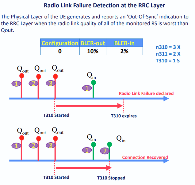
4- Radio Link Failure Detection(RLF)
- The Physical Layers of the UE Can use the CSI-RS to generate in-Sync & Out-of-Sync Indications.
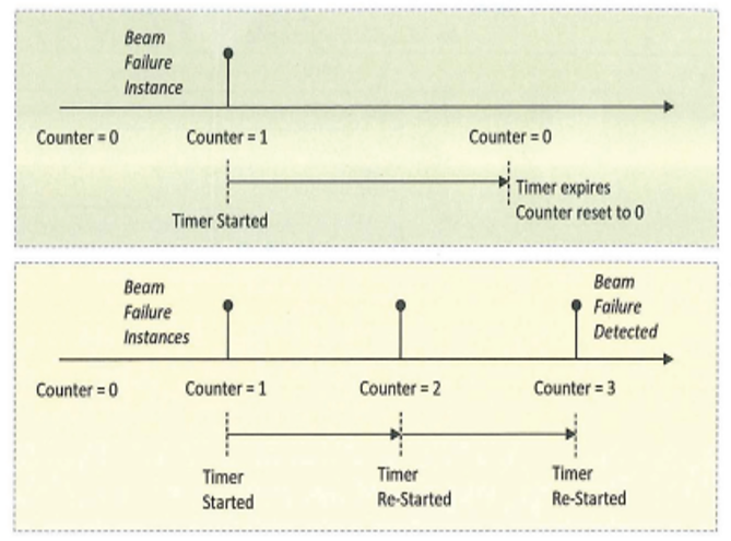
5- Beam Failure Detection and Recovery
- The UE uses CSI-RS to generate ''Beam Failure Instance" indications.
- These indications are provided to the MAC Layer, which uses them to monitor the beam and detect beam failure when the conditions are poor.
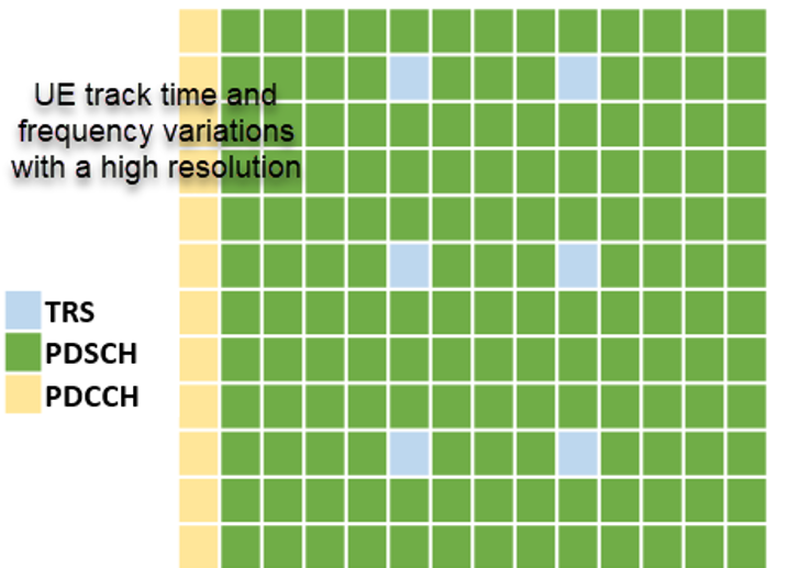
6- Fine Tuning of Time and Frequency Synchronization
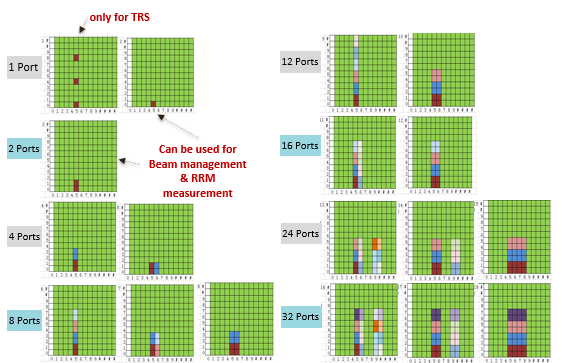
- 3GPP has adopted the CSI-RS as a solution for the TRS.
- The TRS is a DL Transmission that allows the UE to track time/Frequency variations with a high resolution.
(2) CSI-RS Key Characteristics
This part is essential to understand as it will ease understanding of the following sections, especially the part related to the CSI-RS Parameters and Resource allocation.
- Unlike LTE, 5G NR does not have cell-specific reference signals.
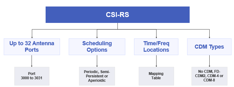
- It must configure reference signals that a device can monitor and report on. These are called CSI-RS, and the Following Figure summarizes the key aspects of the CSI-RS.
- Various configuration options enable the CSI-RS to be sent on multiple ports with various scheduling options such as Periodic, Semi Persistent, and Aperiodic.
Now let's further explore the mentioned CSI-RS characteristics.
(1) CSI Antenna Ports:
- CSI Supports up to 32 Antenna Ports from Port 3001 to 3031
- A configured CSI-RS may correspond to up to 32 antenna ports, each corresponding to a channel to be sounded. (This means more ports = more overhead)
- 32 port CSI-RS provides better granularity in the beamforming but will increase CSI Overhead.
(2) Scheduling Options
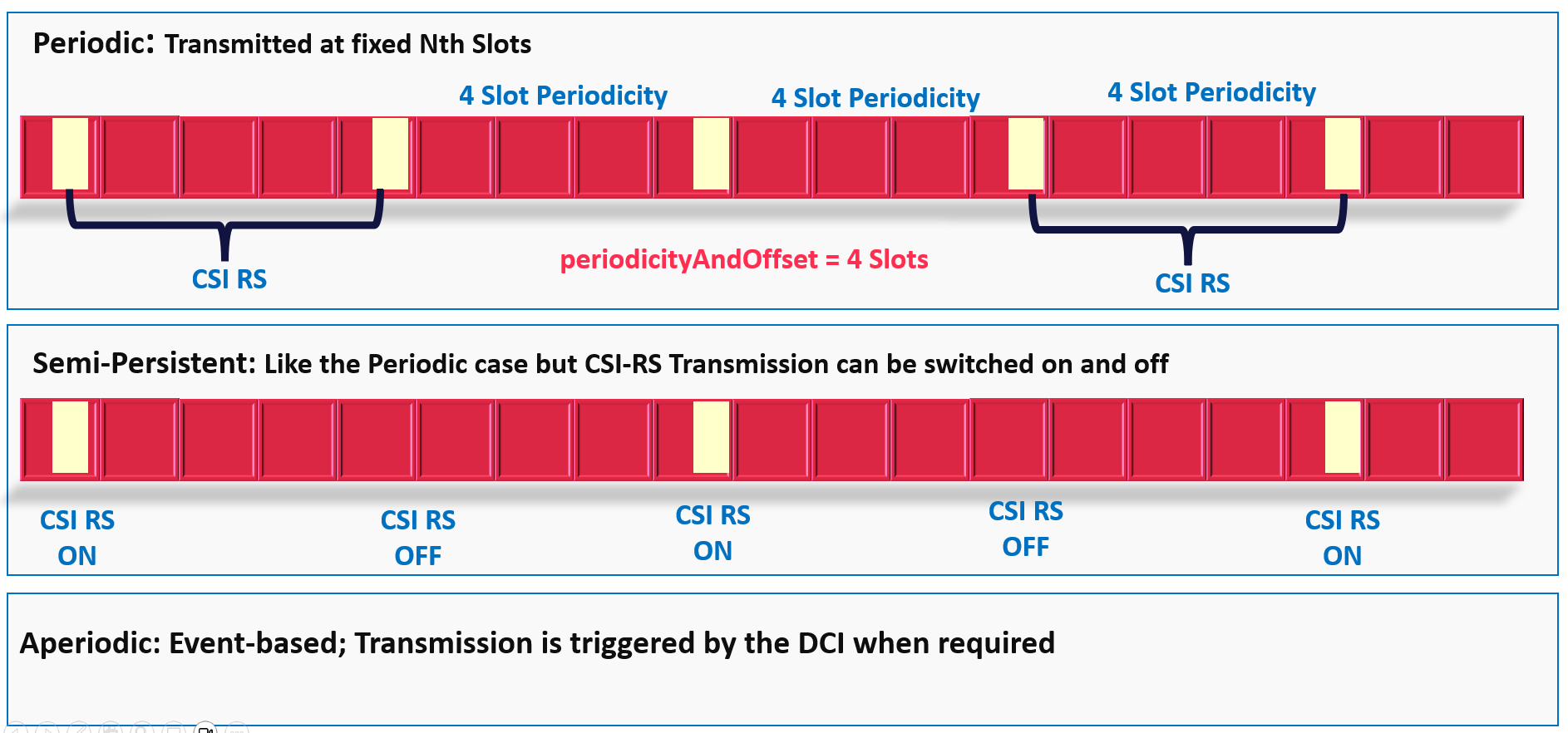
CSI-RS occurrences in the time domain can be scheduled in three ways: periodic, semi-persistent, and aperiodic.
- Periodic CSI-RS: The gNodeB periodically transmits CSI-RS to UEs by the configured period, and UEs receive CSI-RS in the same period. (This is the most common used in all networks)
- Semi-persistent: This is the same as periodic, but transmission can be momentarily suspended.
- Aperiodic: Transmission happens without a pre-defined schedule. UE has to be notified of such transmission with downlink control information or DCI.
(3) Time & Frequency Locations for CSI-RS
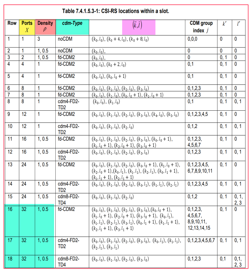
- In terms of location, a specific time/frequency location table defines where in the slot the CSI-RS are sent and other aspects, such as CDM (Code Division Multiplexing) options.
- I will explain the below tables in the resource allocation part(Section 5)
Where:
- Ports: A configured CSI-RS may correspond to 1 to 32 different antenna ports, each corresponding to a channel to be sounded.
- Density quantifies the number of Res allocated to the CSI RS per RB per Port.
- CDM-Type is applicable when multiple ports share the same RE allocation. In this case, code division multiplexing is used to differentiate the transmissions from each port. Example Fd-CDM2 means that CDM is used to differentiate 2 REs occupying different subcarriers, and Cdm4-FD2-TD2 means that CDM is used to differentiate 2 REs, which occupy a grid of 2 subcarriers X 2 Symbols.
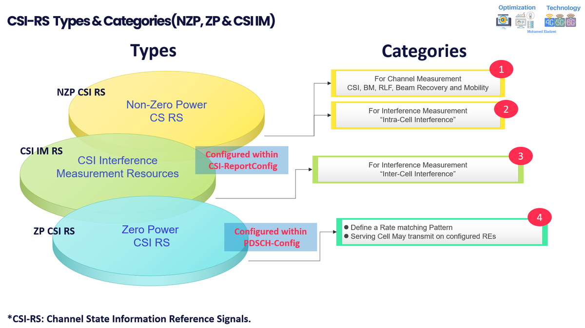
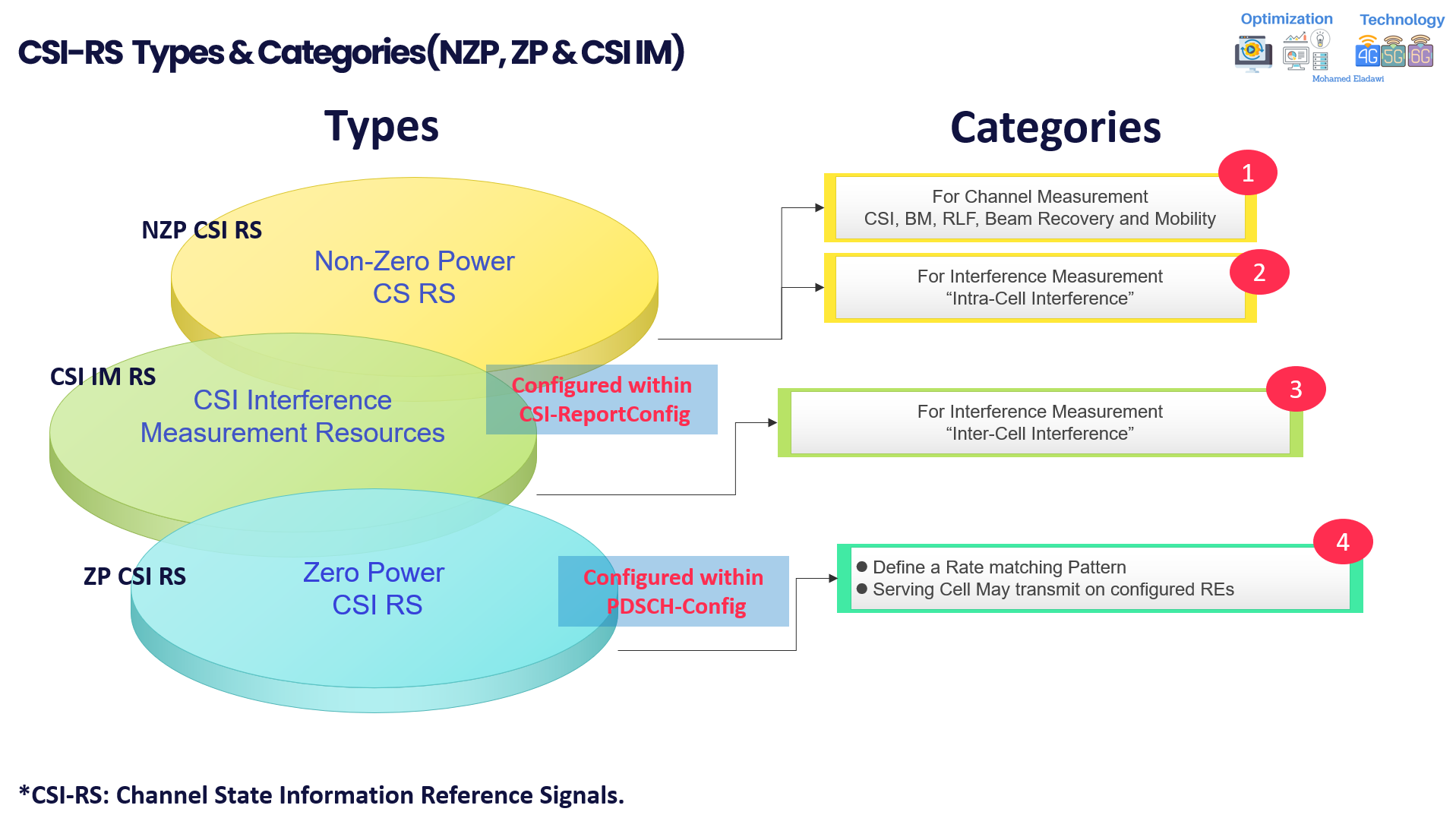
(3) CSI-RS Types & Categories(NZP, ZP & CSI IM)
The following is the CSI-RS 3 Types, which is summarized in the below figure:
- Non-Zero Power CS RS is used for two main purposes:
- For Channel Measurement CSI reporting, Beam Management, RLF, Beam Recovery, and Mobility.
- For Interference Measurement, “Intra-Cell Interference” is mainly used to measure intra-Cell interference generated by
- Users during Multi-User MIMO (Example will be given in the following sections.
- CSI Interference Measurement Resources
- Mainly used for For Interference Measurement, “Inter-Cell Interference” measures the interference reported or detected from Neighbors cells during SU-MIMO
- Zero Power CSI RS
- Define a Rate matching Pattern
- Serving Cell May transmit on configured REs
Now let's further explore CSI-RS Types with some examples
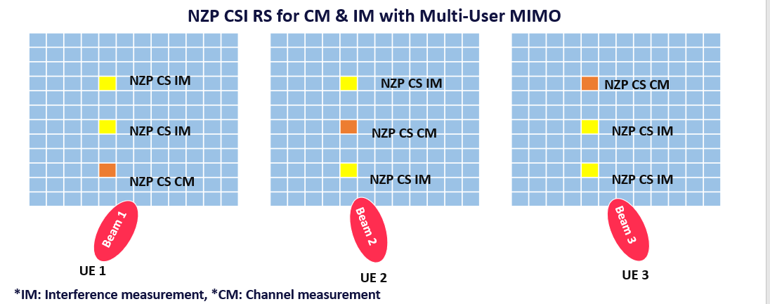
- Non-Zero Power CS RS
- The Below figure illustrates an example MU MIMO Scenario which involves 3 UE being allocated a common set of Resource Blocks and symbols.
- Each UE is configured with 2 NZP CSI RS resources for IM and 1 NZP CSI RS resource for CM.
- The Resources are configured such that 2 UE complete IM while the 3rd UE receives its NZP CSI RS for CM, i.e., 2 UE measures the interference levels generated when transmissions are scheduled towards the 3rd UE.
- This allows each UE to generate CQI reports which reflect the MU MIMO radio conditions.
💡
Refer to the video at the end of this article if you are still having trouble understanding the example below.
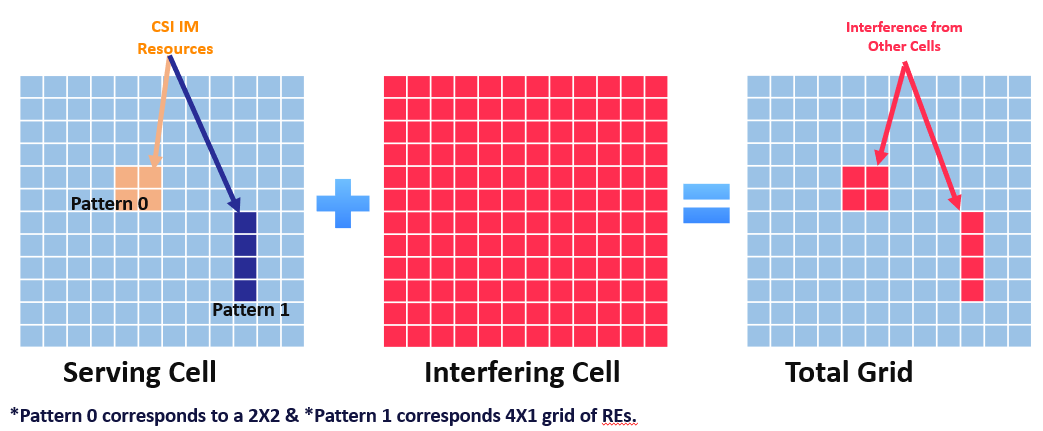
- CSI Interference Measurement Resources(CS IM Resources)
- 3GPP Specified a third category of CSI Reference Signal resources that can be used for detecting interference from the neighbor Cells.
- The Resource element configured for this purpose may be used to measure background interference Levels.
- The serving cell does not transmit anything within these Resource elements so that the UE can measure background interference originating from the NBR Cells
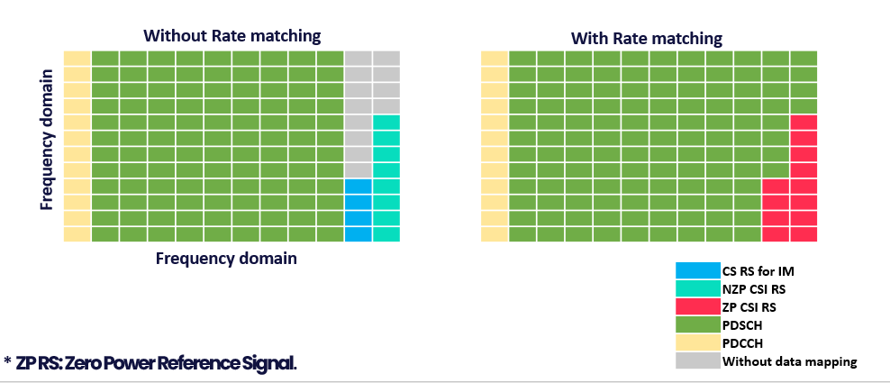
- ZP RS“CSI-RS rate matching.
- On a time-domain OFDM symbol, CSI-RS for IM or NZP CSI-RS occasionally does not fully occupy the corresponding frequency-domain resources. as per the specifications, ZP CSI-RS is used to inform UEs of the REs that are not mapped onto any data, as shown in the figure below.
- The gNodeB uses ZP CSI-RS resources to inform UEs of the remaining frequency-domain resources for mapping data, thereby increasing the number of available REs of the UEs.
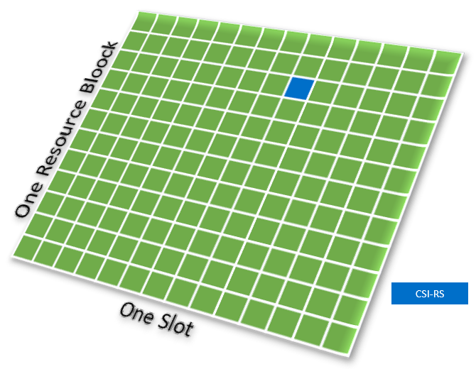
(4) BASIC CSI-RS STRUCTURE
Before Jumping into the Parameter description and Resource allocation section, let me first explain the basic structure of CSI-RS.
- A single-port CSI-RS occupies a single resource element within a block corresponding to one resource block in the frequency domain and one slot in the time domain.
- A configured CSI-RS may correspond to up to 32 different antenna ports.
- In NR, a CSI-RS is always configured on a per-device basis.
- The CSI-RS can be configured to occur anywhere within the Resource block.
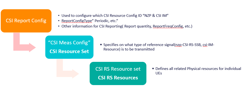
(5_ CSI-RS Main Parameters ”Layer 3 messages”
- Before jumping into parameter descriptions, let`s look into Layer 3 Parameters Structure & Frame of CSI Report.
- Usually, when you check the L3 message, you will see the below hierarchy/structure as shown in below figure
CSI-RS Main Parameters Description:
- The below table summarizes CSI-RS Main related parameters:
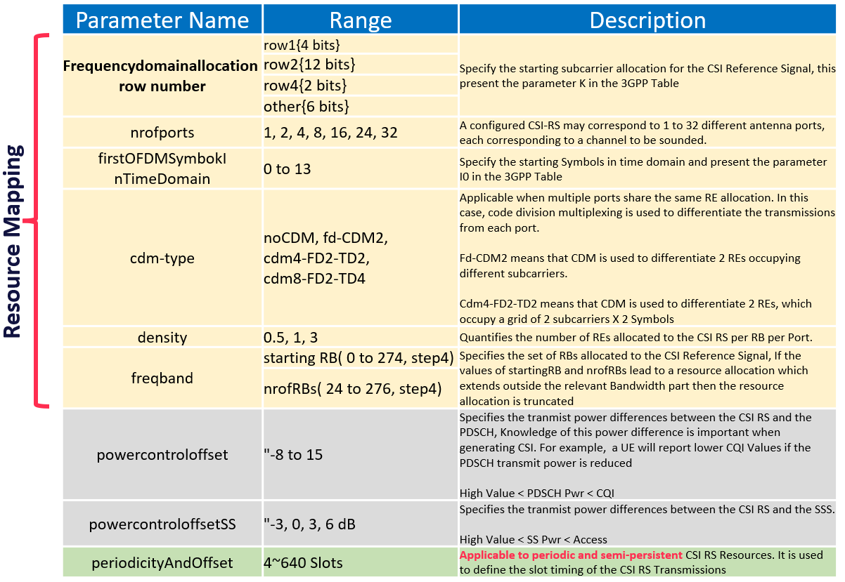
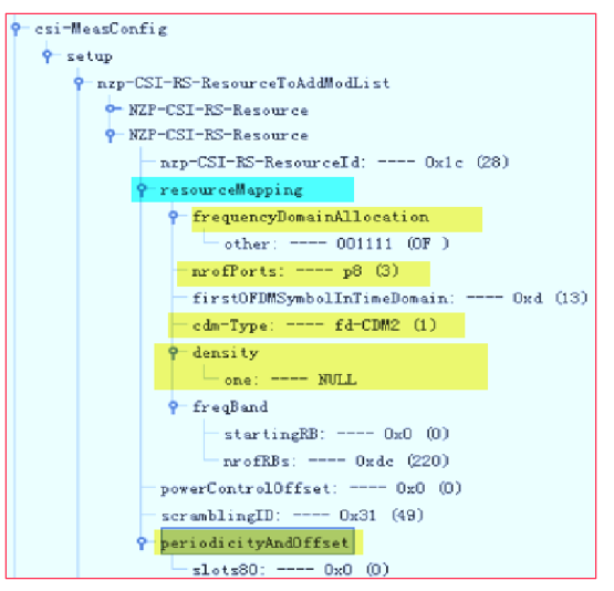
- The above mentioned parameters can be checked from Layer 3 message, as show in the below figure
- In SA networking, check the traced RRCReconfiguration message” CSI-MeasConfig” and “PDSCH-CONFIG.”
- In NSA networking, check the SgNB Addition Request Acknowledge.
(6) UE Capability Check
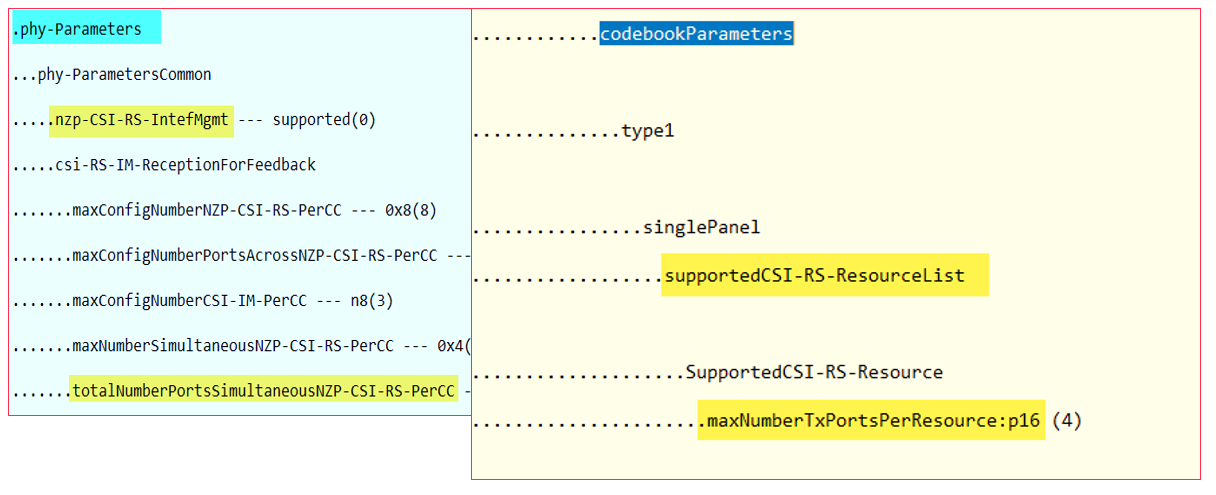
- According to 3GPP Release 15, the codebook Parameters IE reported by a UE indicates the maximum configurable CSI-RS for CM resources for the UE.
- Specifically, it indicates only the maximum configurable CSI-RS for CM resources for UEs operating in a single frequency band. For details, see section 6.3.3 "UE capability information elements" in 3GPP TS 38.331.
- The codebook Parameters IE indicates the maximum configurable CSI-RS for CM resources for UEs operating in a single frequency band. UEs always report it and does not need to be queried by the base station.
- The codebookParametersPerBand-r16 IE also indicates the maximum configurable CSI-RS for CM resources for UEs operating in a single frequency band. It is reported by UEs only after the base station delivers the codebookTypeRequest-r16 IE.
(5) Frequency & Time Domain Structure of CSI-RS Configurations
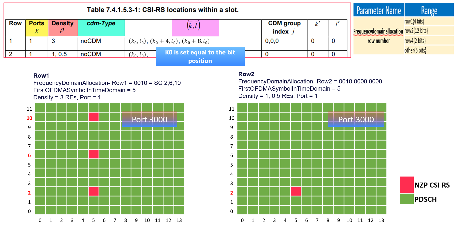
- As highlighted earlier in this article, the Frequency & Time domain allocations are controlled by a 3GPP table that defines where in the slot the CSI-RS are sent and other aspects, such as CDM (Code Division Multiplexing) options. "The table picture was shared earlier under CSI-RS Key Characteristics section"
- I will share a sample of this table to explain how the UE decodes the information sent in the 3GPP Table, and for more clear figure, you can refer to the below videos which covers more examples of the resource allocation.
- The example given below is for the CSI Reference Signal for rows 1 and 2.
- Row 1 is a special case because it has a high density when compared to all other rows. The tracking Reference Signal uses this configuration, It is also intended for Beam Management procedures.
- The High density of Resource elements helps to improve measurement accuracy.
- Row1 & 2 use single port transmission so code division multiplexing is not necessary
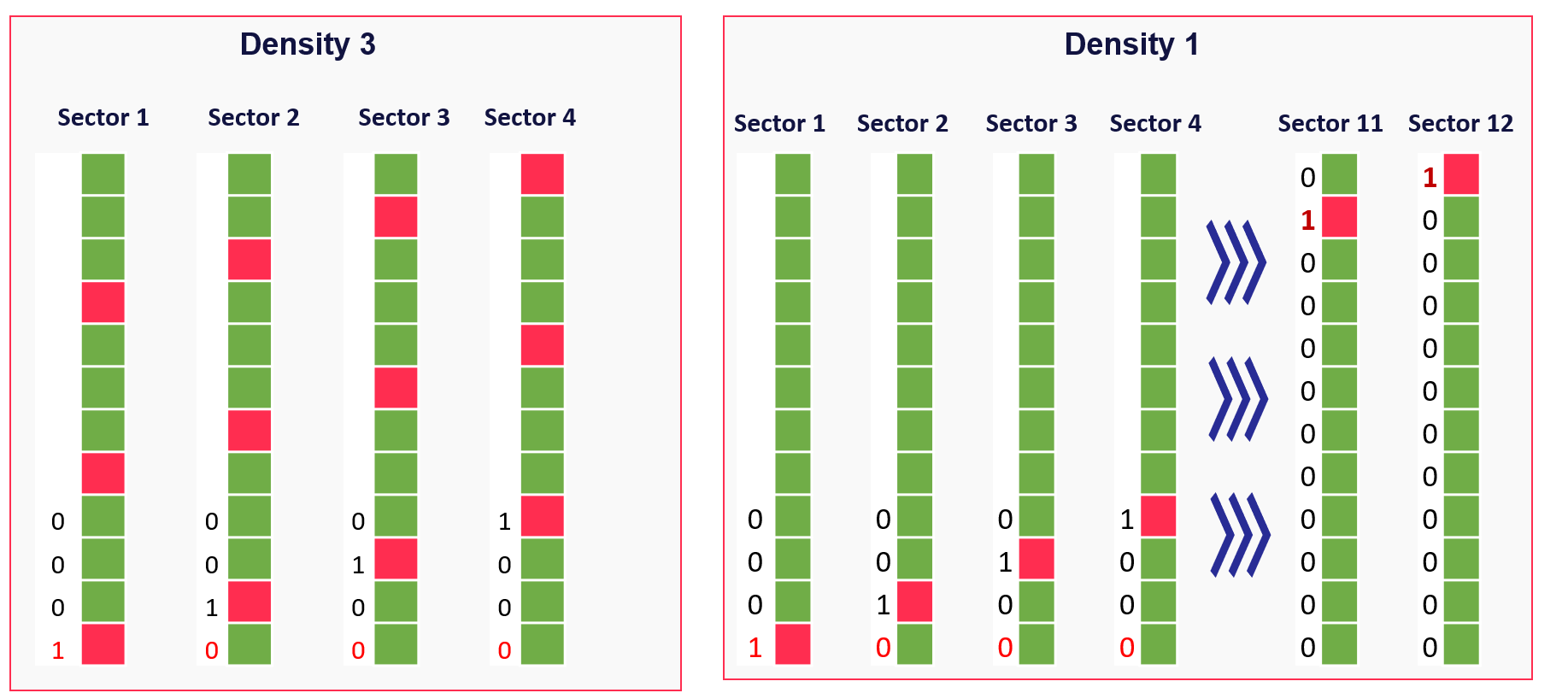
(7) CSI Reference Signal Planning
- The requirement for planning will depend upon the use case and the network implementation.
- The Vendor may provide a choice of CSI RS Densities, Densities 0.5, 1, and 3 RE per RB are supported
- Higher density allows the UE to complete its measurements with increased accuracy but Higher Overhead
- Configuring Lower density increases the scope for Frequency Multiplexing
YouTube videos for the same:
Part 1
Part 2
Sources:
- 5G NR in Bullets
- 3GPP TS 38.331