E2E 5G NSA Accessibility Signaling and Failures Analysis guide(Article + Video)

Introduction:
This Article is a deep dive into 5G NSA Accessibility Signaling overview and Failures Possible Causes & Troubleshooting Methods.
The following topics are covered in this article:
- NSA(ENDC) Network Overview
- 5G Secondary Node Addition procedure
- SgNB addition triggering Scenarios
- High-level procedure for adding a secondary node
- E2E SN Addition Signaling Call Flow + Signaling Key Information Elements Contents
- 3GPP TS 37.340- Secondary Node Addition procedure details
- 5G NSA Troubleshooting Guide: Identification of Accessibility Issues
5G NSA(ENDC) Network Overview
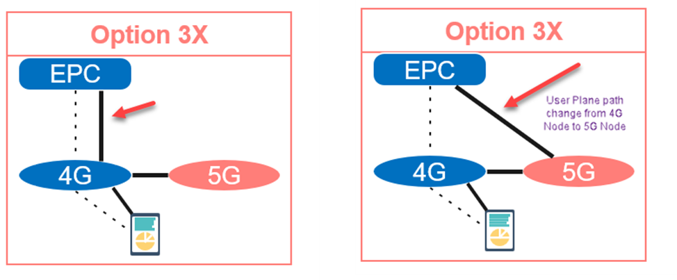
(A) 5G NSA Option 3X Architecture
- Before delving into the details, let's first recap the simplified network architecture of 5G NSA (Non Standalone).
- 5G Non Standalone signifies that the deployment of the 5G Network still relies on the existing 4G Network (RAN & Core).
- In this setup, the 4G Network serves as an anchor to the 5G. In simpler terms, most current deployment scenarios utilize the Option 3X Architecture.
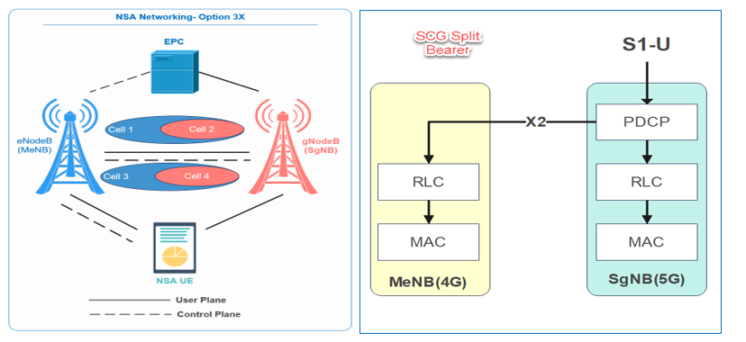
- Here, all signaling and control planes are managed through the 4G eNodeB, and data split occurs on the SgNB.
- The data split bearer primarily supports SCG Split Bearer, indicating that user-plane data is split at the PDCP layer of the SgNB, distributed to the RLC layers of the MeNB and SgNB, as illustrated in the figure below, and then aggregated at the PDCP layer of the UE.
In summary:
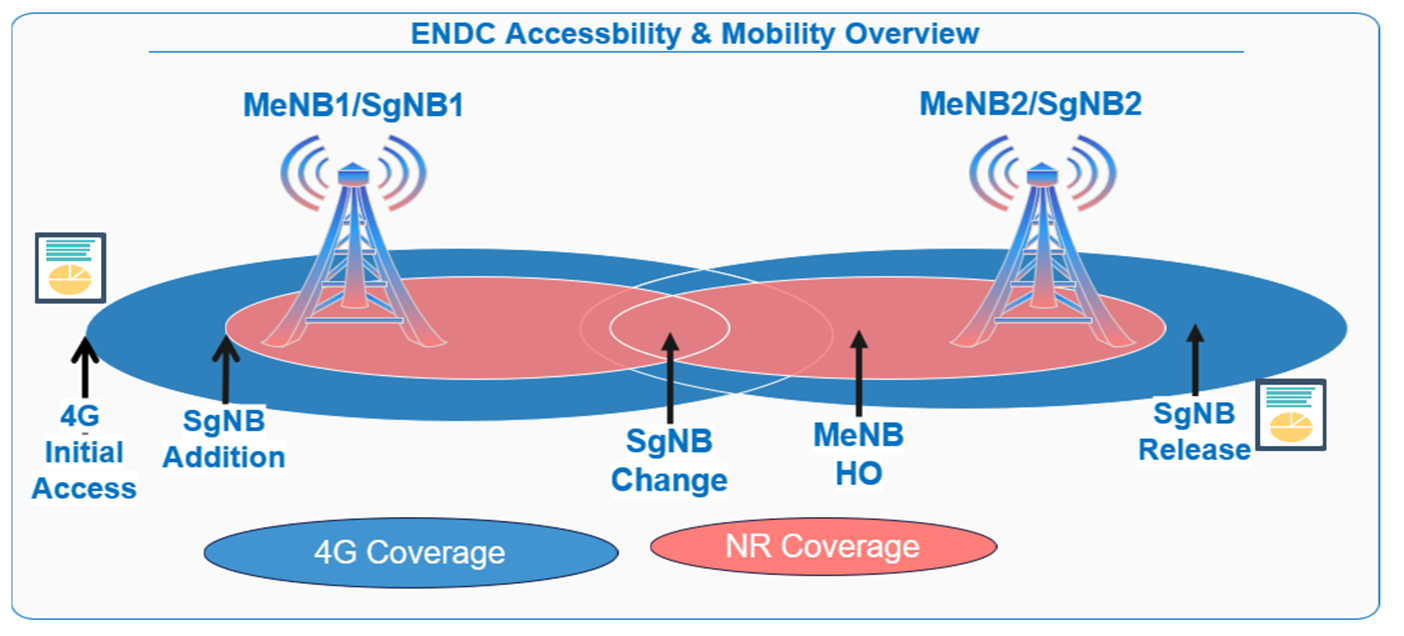
- 5G NSA can be deployed in areas where LTE and NR network coverage overlap.
- The network architecture utilized depends on how the eNodeB/gNodeB and the EPC are interconnected.
Related Concepts
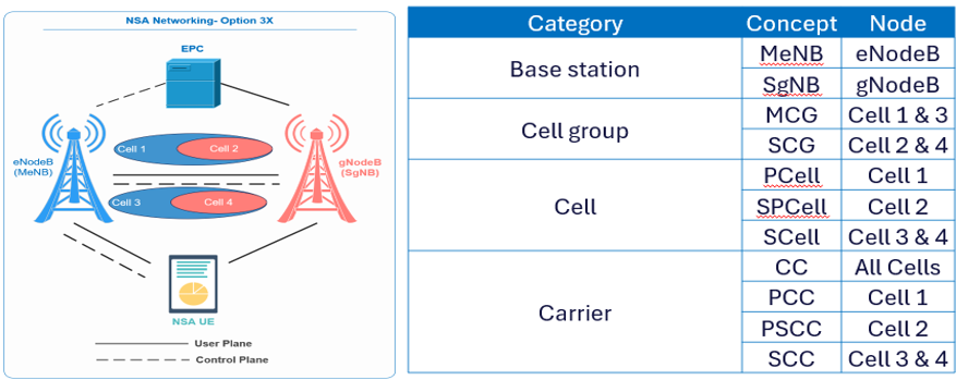
- This section utilizes the picture and table below to illustrate the concepts related to NSA networking. In this example:
- Carrier aggregation is carried out separately on the eNodeB and gNodeB sides, followed by providing Dual Connectivity (DC) for the NSA UE.
- Each carrier corresponds to a cell. Cells 1 and 3 represent co-coverage cells of the eNodeB, while cells 2 and 4 represent co-coverage cells of the gNodeB.
Where:
- PCell: The Primary Cell (PCell) of the NSA UE is a cell served by the MeNB on which the UE is camping.
- PSCell: The Primary SCG Cell (PSCell) of the NSA UE is a primary cell served by the SgNB and configured for the UE through an RRC message sent by the MeNB. During SgNB Addition, the eNodeB delivers an RRC Reconfiguration message containing all relevant parameters and configurations for the PScell (SpCell), which will be covered in this article.
- SCell: A Secondary Cell (SCell) of the NSA UE is a cell served by either the MeNB or SgNB and configured for the UE through an RRC message sent by the MeNB. This cell can provide the UE with additional radio resources. (For example, Cells 3 and 4 are SCells).
Note: The PUCCH is available in each PCell and PSCell but not available in any SCell.
5G Secondary Node Addition procedure:
In this section, we'll deep dive into the signaling call flow of Secondary Node addition.
(A) SgNB addition triggering Scenarios:
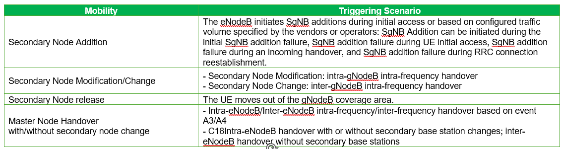
- The eNodeB triggers SgNB additions during initial access or when specified traffic volume thresholds are met, as set by vendors or operators.
- SgNB addition may occur in the following scenarios:
- Initial SgNB addition
- After SgNB addition failure
- SgNB addition during an incoming handover or SCell Change
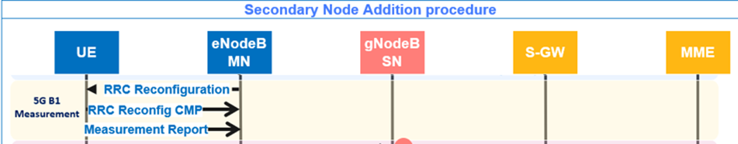
(B) High-level procedure for adding a secondary node
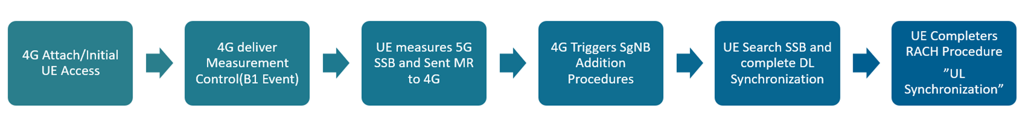
The general process is illustrated in the figure below.
- Assuming the UE is in Idle mode, the first step is to initiate the initial access procedure to establish the UE context.
- After the UE transitions to a connected state, the eNodeB provides the necessary configuration for the NR B1 event to enable SgNB addition measurements.
- Once the UE receives the B1 configuration, it measures the 5G SSB and reports the measurement results to the 4G network if the specified B1 event conditions are met.
- Upon receiving the measurement report, the eNodeB initiates the SgNB addition procedure and instructs the UE to add the NR SpCell by sending all necessary information through an RRC Reconfiguration message.
- The UE then completes DL synchronization with the NR cell and initiates RACH procedures towards the gNB to establish UL synchronization.
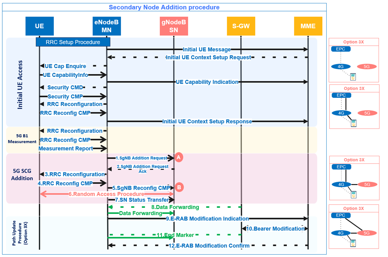
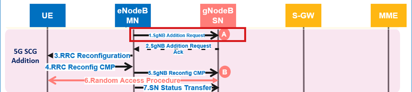
(C) E2E SN Addition Addition Signaling Call Flow + Messages Contents
- Now, let’s review the most important signaling message contents for the end-to-end Secondary Node Addition procedure:
- The below figure shows the E2E 5G Addition Call flow for NSA Option 3X starting from 4G Idle till path update procedures:
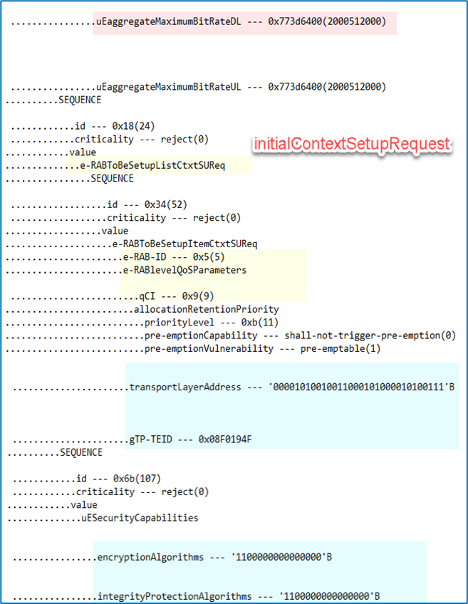
(1) Initial UE Context Setup Request:
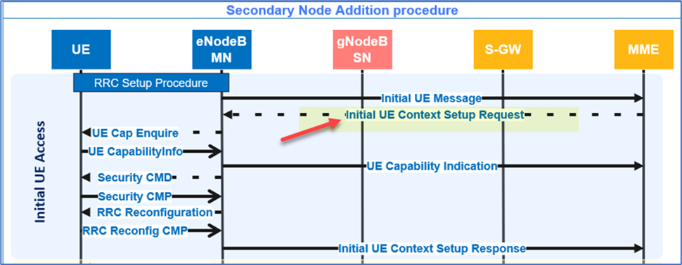
- The below table summarizes the mandatory and optional messages contents:
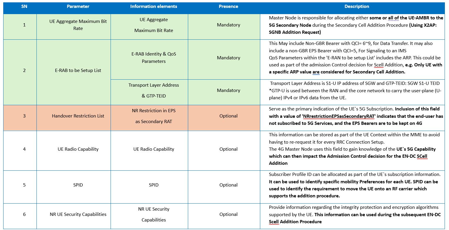
- This is how the Initial UE Context Setup Request contents will looks like from the traces
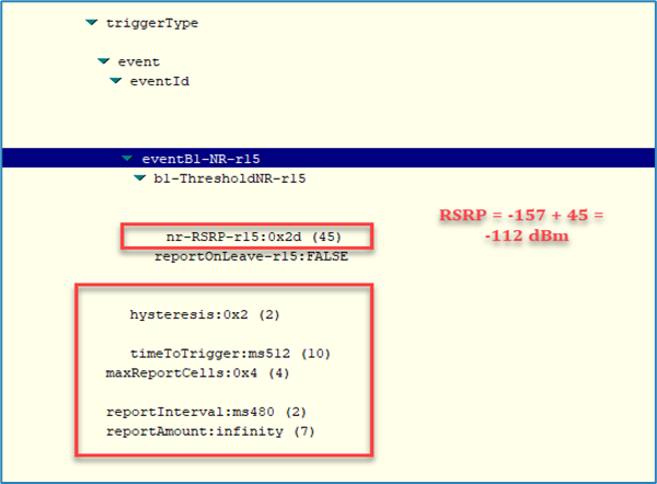
(2) 4G RRC Reconfiguration and Measurement Report
- RRC Reconfiguration: Initially, the gNB provides the NR Event B1-related thresholds, as illustrated in the figure below:
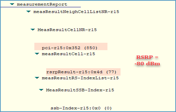
- Measurement Report: The UE initially reports the RSRP and RSRQ of the best serving cells once the specified B1 Event thresholds are met.
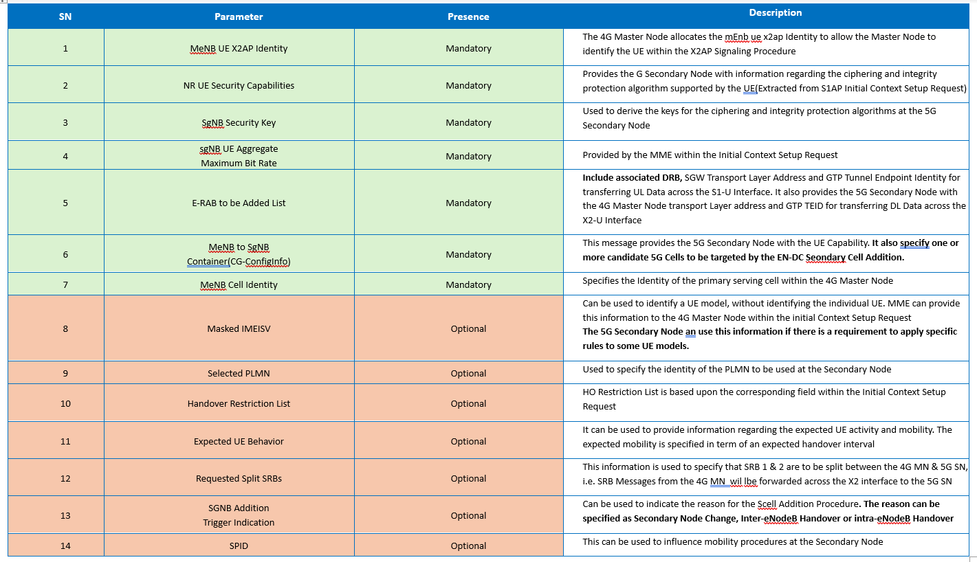
(3) SgNB Addition Request:
- In the SgNB Addition Request message, the eNodeB will provide the following parameters to the gNodeB:
- ERAB ID and DRB mapping information
- ENDC (Evolved-Universal Terrestrial Radio Access-New Radio Dual Connectivity) bearer type
- ERAB QoS (Quality of Service) parameters
- eNodeB IP address and Tunnel Endpoint ID (TEID) for X2-U
- Serving Gateway (SGW) IP address and TEID for S1-U
- UE (User Equipment) NR capabilities
- Target gNodeB cell measurement information
- The below table summarizes the mandatory and optional messages contents:
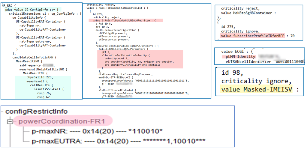
- What does the SgNB Addition Request look like in the traces? Below are the most important contents:
- Candidate cell information: Indicate the target cell PCI and SSB RSRP
- Maximum allowed UE Power For EUTRAN & NR, each 20 dBm
- E-RAB QoS parameters
- MeNB-DL-GTP-TEID at MCG: eNodeB IP and TE ID for X2-U spilt bearer
- S1-UL-GTPtunnelEndpoint: SGW IP and TEID (Option3x)
- Masked-IMEISV: information which can be used to get the device type.
- SPID: Subscriber profile ID Feature
(4) SgNB Addition Request Ack:
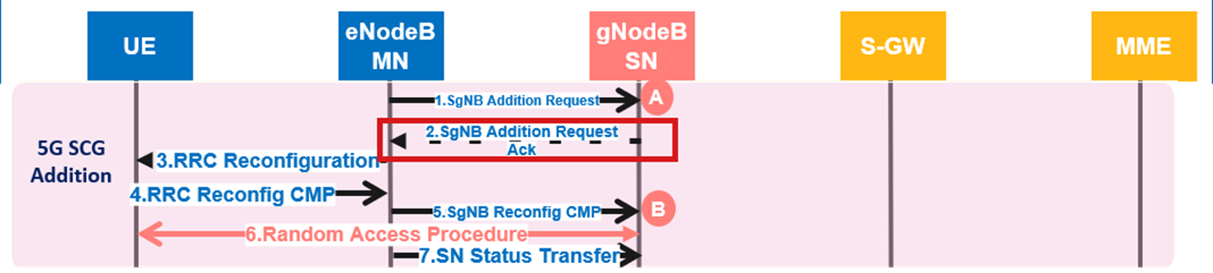
- The SgNB Addition Acknowledgment message will include the following key information from the gNodeB:
- NR cell configuration, which will be relayed to the UE via LTE messaging.
- gNodeB IP address and Tunnel Endpoint ID (TEID). Two TEIDs will be assigned for the S1-U IP path and X2-U split bearer, while an additional two TEIDs will be designated for temporary data forwarding during the SCG addition procedure.
- The below table summarizes the mandatory and optional messages contents:
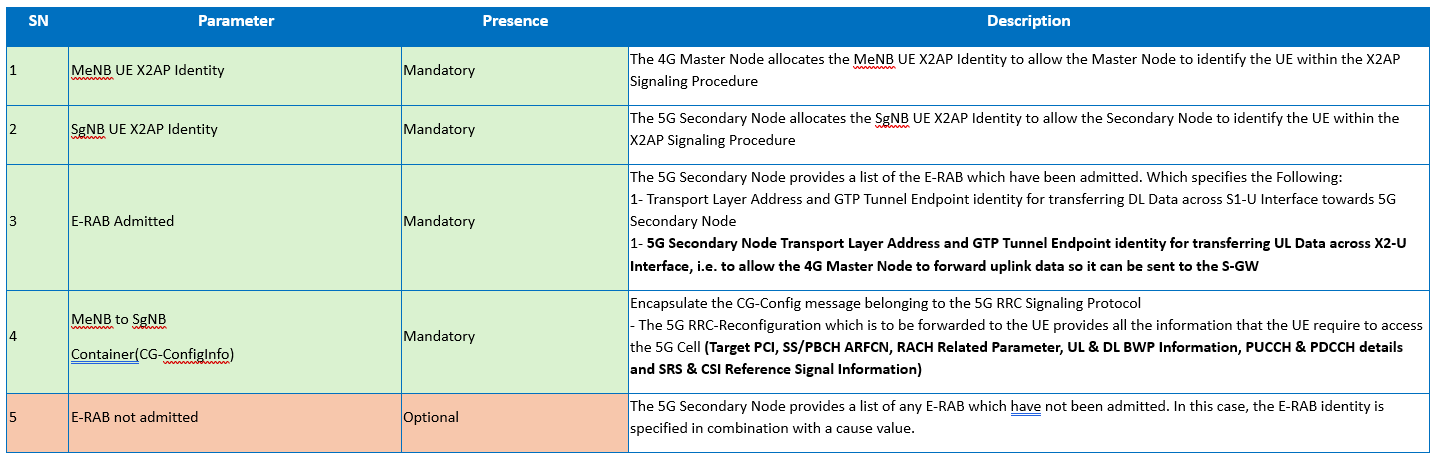
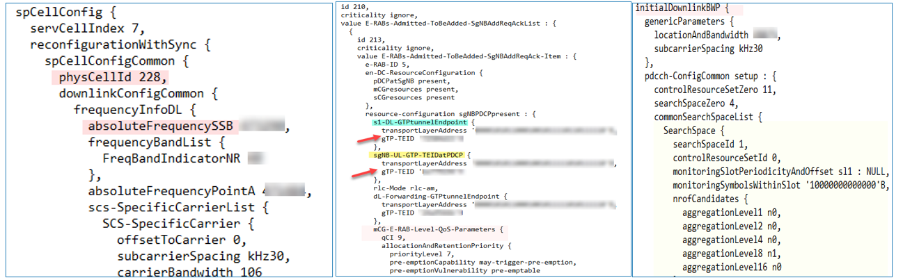
- What does the SgNB Addition Request Acknowledgment look like in the traces? Below are the most important contents:
- SgNB IP and TEID for S1 IP path.
- SgNB IP and TEID for X2 split bearer.
- SgNB IP and TEID for X2 DL forwarding bearer during the addition procedure.
- SgNB IP and TEID for X2 UL forwarding bearer during the addition procedure.
- MCG E-RAB QoS Parameter.
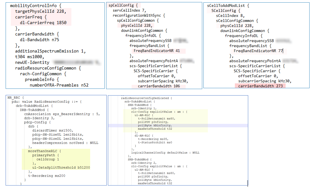
(5) RRC Reconfiguration:
- After receiving the ACK message from the gNodeB, the eNodeB transmits the NR configuration details to the UE over the air interface.
- This message includes all cell configuration parameters relevant to the NR side, consisting of the following components settings for RLC/MAC/PHY and spcellConfig for the primary NR cell:
- spCellconfiguration: This section includes ReconfigWithSync (for initial access synchronization), RLF (Radio Link Failure) timer, and spCelldedicated. The ReconfigWithSync component incorporates spCellcomm and RACH dedicated (non-contention-based random access for NSA).
- MeasConfig: This conveys the measurement configuration specific to NR.
- SCG-RB-Config: This delivers parameters for uplink traffic split and the primary data path.
- What does the RRC Reconfiguration message look like in the traces? Below are the key contents:
- SCG RLC/MAC/PHY Protocol Layer Configuration: This pertains to the protocol layer configuration specifically for the Secondary Cell Group (SCG) in the NR context.
- ReconfigWithSync: This includes parameters related to UE random access, comprising both common and dedicated configurations.
- spCellConfigDedicated: This configuration is utilized to set up the dedicated Bandwidth Part (BWP) for the UE within the Secondary Cell Group (SCG).
- NR A2/A3 Event Measurement Configuration for NSA Mobility: This specifies the configuration for NR mobility event measurements (A2/A3 events) relevant to Non-Standalone Access (NSA) scenarios.
- SCG UL Data Split Parameters: These parameters define the parameters for splitting uplink (UL) data within the Secondary Cell Group (SCG).
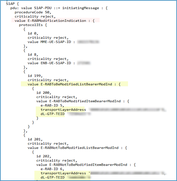
(6) E-RAB Modification Indication:
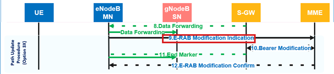
- The 4G Master Node initiates the signaling which is used to move the S1-U connection from the 4G Master Node to the 5G Secondary Node.
- This is done by sending an S1AP: E-RAB Modification Indication to the MME.
- The E-RAB to be modified List provides the Transport Layer Address and DL GRP TEID provide by the 5G Secondary Node within the X2AP: SGNB Addition Request Acknowledge.
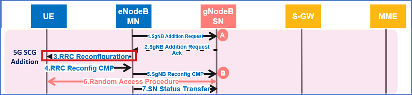
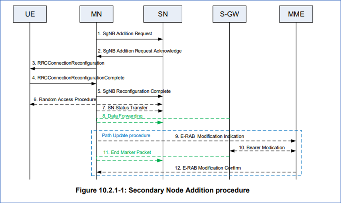
(D) 3GPP TS 37.340- Secondary Node Addition procedure details
Below are the steps of the Secondary Node Addition procedure details and the corresponding call flow diagram, as referenced from 3GPP TS 37.340:
The MN decides to request the SN to allocate resources for a specific E-RAB, indicating E-RAB characteristics (E-RAB parameters, TNL address information corresponding to bearer type).
- In addition, for bearers requiring SCG radio resources, MN indicates the requested SCG configuration information, including the entire UE capabilities and the UE capability coordination result.
- In this case, the MN also provides the latest measurement results for SN to choose and configure the SCG cell(s).
- The MN may request the SN to allocate radio resources for split SRB operation.
- If the RRM entity in the SN is able to admit the resource request, it allocates respective radio resources and, dependent on the bearer option, respective transport network resources.
- For bearers requiring SCG radio resources, the SN triggers Random Access so that synchronization of the SN radio resource configuration can be performed.
- The SN decides the PSCell and other SCG SCells and provides the new SCG radio resource configuration to the MN in a NR RRC configuration message contained in the SgNB Addition Request Acknowledge message.
- The MN sends to the UE the RRCConnectionReconfiguration message including the NR RRC configuration message, without modifying it.
- The UE applies the new configuration and replies to MN with RRCConnectionReconfigurationComplete message, including a NR RRC response message, if needed. In case the UE is unable to comply with (part of) the configuration included in the RRCConnectionReconfiguration message, it performs the reconfiguration failure procedure.
- The MN informs the SN that the UE has completed the reconfiguration procedure successfully via SgNB ReconfigurationComplete message, including the encoded NR RRC response message, if received from the UE.
- If configured with bearers requiring SCG radio resources, the UE performs synchronization towards the PSCell of the SN. The order the UE sends the RRCConnectionReconfigurationComplete message and performs the Random Access procedure towards the SCG is not defined. The successful RA procedure towards the SCG is not required for a successful completion of the RRC Connection Reconfiguration procedure.
- In case of SN terminated bearers using RLC AM, the MN sends SN Status Transfer.
- In case of SN terminated bearers using RLC AM, and dependent on the bearer characteristics of the respective E- RAB, the MN may take actions to minimize service interruption due to activation of EN-DC (Data forwarding).
- 9-12. For SN terminated bearers, the update of the UP path towards the EPC is performed.
5G NSA Troubleshooting Guide: Identification of Accessibility Issues
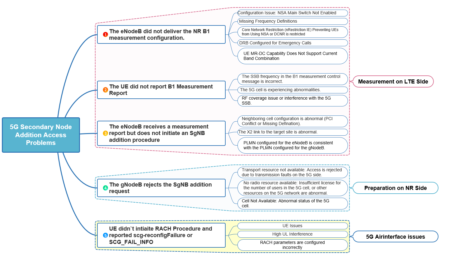
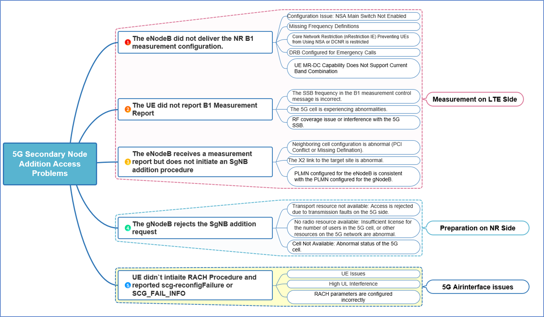
This section describes the user access process and common fault demarcation methods to preliminarily isolate and locate access problems. The most common failures can be categorized and classified into the 5 main parts:
- The eNodeB did not provide the NR B1 measurement configuration, which is most likely due to one of the following reasons:
- Configuration Issue: NSA Main Switch Not Enabled.
- Missing Frequency Definitions.
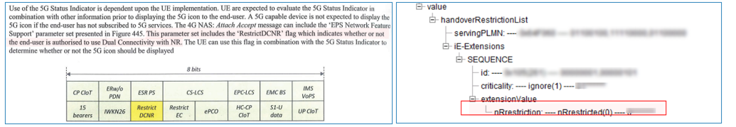
- Core Network Restriction (nRestriction IE) Preventing UEs from Using NSA or DCNR is restricted.
- DRB Configured for Emergency Calls.
- UE MR-DC Capability Does Not Support Current Band Combination.
- The UE did not report B1 Measurement Report, which is most likely due to one of the following reasons:
- The SSB frequency in the B1 measurement control message is incorrect.
- The 5G cell is experiencing abnormalities.
- RF coverage issue or interference with the 5G SSB.
- The eNodeB receives a measurement report but does not initiate an SgNB addition procedure, which is most likely due to one of the following reasons:
- Neighboring cell configuration is abnormal (PCI Conflict or Missing Definition).
- The X2 link to the target site is abnormal.
- PLMN configured for the eNodeB is consistent with the PLMN configured for the gNodeB.
- The gNodeB rejects the SgNB addition request, which is most likely due to one of the following reasons:
- Transport resource not available: Access is rejected due to transmission faults on the 5G side.
- No radio resource available: Insufficient license for the number of users in the 5G cell, or other resources on the 5G network are abnormal.
- Cell Not Available: Abnormal status of the 5G cell.
- The UE didn`t initiate RACH Procedure and reported scg-reconfigFailure or SCG_FAIL_INFO, which is most likely due to one of the following reasons:
- UE Issues.
- High UL Interference.
- RACH parameters are configured incorrectly.
YouTube video for the same:
Materials for the same uploaded below:
Sources:
- 3GPP TS 37.340
- 3GPP TS 38.423
- 5G NR in Bullets