Master EPS Fallback in 5G SA - (Article + Video)

Introduction
This Article is a deep dive into 5G Voice EPS Fallback, covering "Everything You Need to Know."
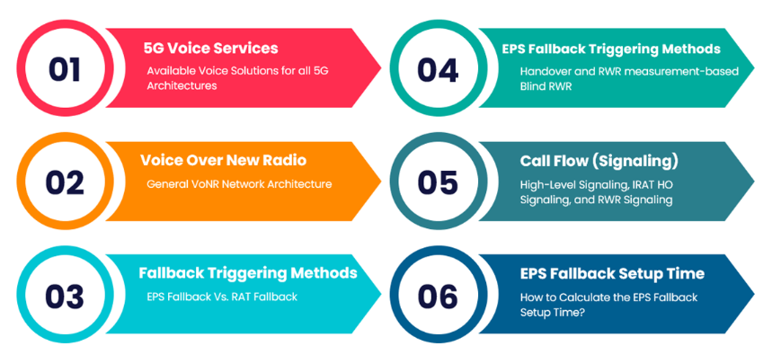
The following topics are explored in this article:
- 5G Voice Services: Comprehensive exploration of all available voice solutions for all 5G architectures.
- Voice Over New Radio: In-depth explanation of VONR Architecture and IMS NW Functions.
- Fallback Triggering Methods: Listing the core differences between EPS Fallback and RAT Fallback.
- EPS Fallback Triggering Methods: Detailed exploration of the main triggering methods for Fallback.
- Call Flow (Signaling): In-depth view of signaling call flow for EPS HO and Redirection measurement-based scenarios.
- Explaining How to Calculate the EPS Fallback Setup Time: Clarifying the process of calculating the setup time for EPS Fallback.
- EPS Fallback Failures Common issues.
5G Voice Services
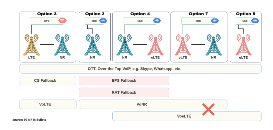
- In 5G, the availability of specific solutions for the voice service depends upon the Base Station architecture. The solutions associated with each architecture are summarized in the figure below.
- All architectures support OTT applications because these only require a data connection, which can be either an EPS Bearer towards the 4G core network or a PDU Session towards the 5G core network.
- For 3/3a/3x, it's 4G Master Node connected to 4G core for legacy voice. CS Fallback and VoLTE work, but CS Fallback may have slight delays due to extra signaling for 5G Secondary Node.
- For 2 and 4/4a, it's 5G Master Node connected to 5G core, requiring new 5G voice solutions like VoNR. No CS Fallback: alternatives are EPS Fallback (4G) and RAT Fallback (5G).
- EPS Fallback redirects UE to LTE Base Station on 4G core, while RAT Fallback redirects UE to 5G Base Station on 5G core.
Note:
- CS Fallback is not supported when using the 5G core network.
- The release 15 version of the 3GPP specifications does not support SRVCC for 5G. Speech service continuity at locations with noncontiguous 5G coverage relies upon Packet Switched inter-system handover towards 4G. SRVCC can then be completed from 4G if necessary.
- SRVCC from 5G to 3G (UTRAN) is planned for the release 16 version of the 3GPP specifications.
Voice Over New Radio
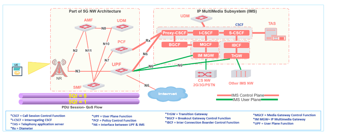
- Both VoNR and VoLTE rely upon connectivity to an IP Multimedia Subsystem (IMS) to manage the setup, maintenance, and release of voice call connections. Session Initiation Protocol (SIP) is used for signaling procedures between the UE and IMS.
- The general network architecture for transferring the user plane speech packets is illustrated in the figure below. The PDU Session provides connectivity between the UE and the UPF, whereas the N6 interface provides connectivity between the UPF and the IMS:
- VoNR uses a QoS Flow with 5QI = 5 to transfer SIP signaling messages. In contrast, VoLTE uses an EPS Bearer with QCI = 5.
Now, lets break down the main functionality of IMS Nodes (CSCF Entities) to better understand how SIP signaling is exchanged. This breakdown can aid in troubleshooting VoLTE or VoNR issues.
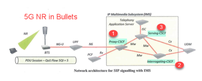
- The Proxy-CSCF is responsible for the following:
- The Proxy-CSCF acts as a first point of contact for the IMS. i.e. all SIP signaling is forwarded through the P-CSCF.
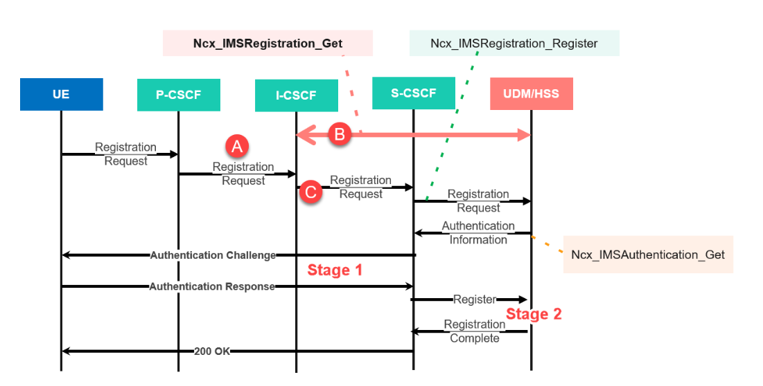
- When a UE completes the registration procedure with the IMS, the P-CSCF is responsible for routing the SIP Register message (PointA in 5G IMS Registration Procedure) towards the Interrogating-CSCF (I-CSCF) . ((I-CSCF function explained below)
- Once the UE has completed registration and a Serving-CSCF (S-CSCF) has been identified, the P-CSCF can forward messages directly to the S-CSCF.
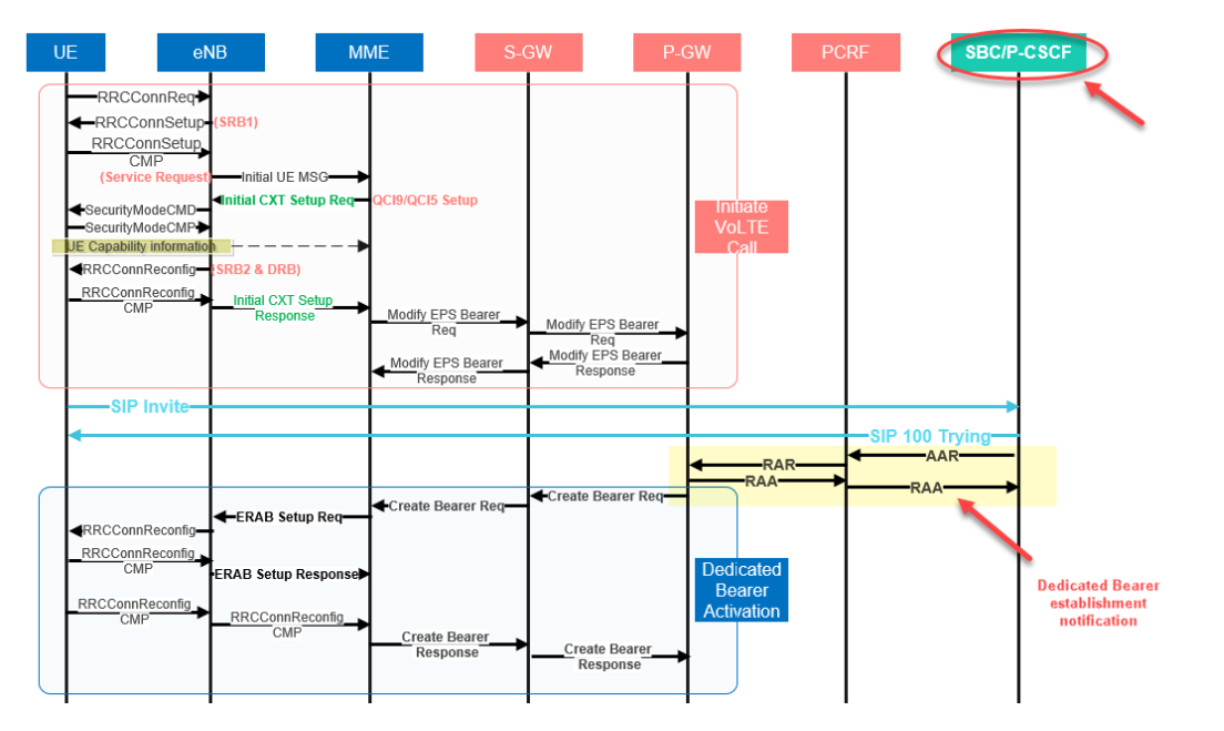
- As shown in below 4G Volte call flow(Partial figure for MO), the P-CSCF communicates with the Policy Control Function (PCF/PCRF) during the setup of VoNR/Volte call. This communication triggers the PCF to initiate the setup of the Qos Flow with 5QI = 1/QCI = 1 (Dedicated Bearer) for the subsequent transfer of speech packets.
Notes:
- P-CSCF connects to PCF/PCRF in the 5G/4G Network through the rx interface.
- P-CSCF uses the RX interface to inform PCRF/PCF about the need for establishing a dedicated bearer for Audio Call dataflow (5QI 1).
- PCF/PCRF then communicates with PGW/UPF then PGW/UPF triggers the establishment of a dedicated bearer for the user plane of Voice.
2. The Interrogating-CSCF (I-CSCF) is mainly responsible for identifying and selecting Serving-CSCF (S-CSCF)
- The Interrogating-CSCF (I-CSCF) communicates with the User Data Management (UDM) function during the IMS registration procedure. (Through Ncx_IMSRegistration_Get as shown in Point B in 5G IMS Registration Procedure)
- The UDM determines whether or not the UE is already registered and provides the identity of the S-CSCF if one has already been allocated. Otherwise, the l-CSCF is responsible for selecting an S-CSCF. (Through Registration as shown in Point C)
3. The Serving-CSCF (S-CSCF) is responsible for the following:
- The Serving-CSCF (S-CSCF) processing and responding to SIP signaling messages from the UE.
- The S-CSCF communicates with the UDM during the IMS registration procedure.
- During the first stage of registration, the S-CSCF obtains an authentication vector from the UDM.
- During the second stage of registration, the S-CSCF informs the UDM that the UE has registered and provides its S-CSCF identity. This allows the UDM to be interrogated in the future when there is a requirement to identify the allocated S-CSCF.
- During a VoNR call setup procedure, the S-CSCF interacts with a Telephony Application Server (TAS) which is responsible for providing the end-user application in combination with supplementary services, e.g. call waiting, call forwarding and call conferencing.
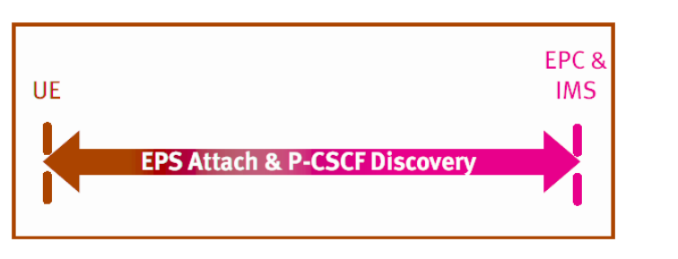
In general, UE has to communicate with all IMS Nodes via Proxy Call Session Control Function(P-CSCF) but interestingly when UE is switched on, it doesn’t know anything about P-CSCF IP address, so how does the UE talk to P-CSCF?
There are several ways for the UE to get P-CSCF IP Address: (IMS Procedure: P-CSCF Discovery)
- It may be stored in the IP Multimedia Services Identity Module (ISIM)
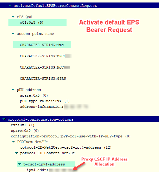
- The UE can request the P-CSCF address in the EPS Attach/Registration or PDN Connectivity Request messages and accordingly the UE will receive the P-CSCF Address in the PDN Connectivity accept messages. (Example from L3 Messages given below)
- UE Can use DHCP procedure for P-CSFC discovery. The UE may request an IP address and Fully Qualified Domain Name (FQDN) from a DHCP server and then perform a DNS query on the returned IP address and FQDN.
So, what role does the LTE/5G network play in supporting VoLTE/VoNR calls?
The main task of the LTE/5G network is to provide IP connectivity to the User Equipment (UE). The UE utilizes this IP connectivity to exchange SIP messages and user plane data with the IMS network.
Now, lets delve into the process followed by the UE to acquire P-CSCF IP Address
When the UE is powered on in 4G/5G networks, it establishes a default bearer with QCI/5QI 6~9. Additionally, VoLTE/VoNR-capable UEs establish another default bearer with QCI/5QI 5 specifically for IMS-related signaling. The Access Point Name (APN) used for this default bearer is always set to IMS. The messages below in Layer 3 demonstrate how the UE requests and receives the PCSCF IP address.
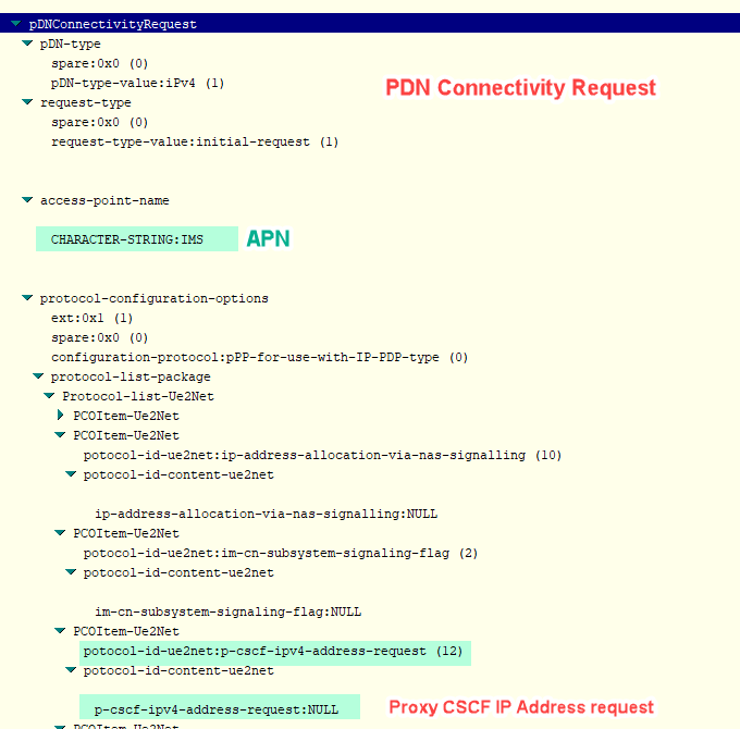
IP addresses are typically represented in Hexadecimal, and you'll need to convert them to decimal to obtain the IP Address. For example, if the Hexadecimal IP is '0A 4E 6D 04,' you can use the following Excel formula for the conversion: '0A 4E 6D 04' → '10.78.109.4'
Excel Formula: 'B3' refers to the hexadecimal IP address."
=TEXT(CONCAT(HEX2DEC(MID(B3, 1, 2)), ".", HEX2DEC(MID(B3, 3, 2)), ".", HEX2DEC(MID(B3, 5, 2)), ".", HEX2DEC(MID(B3, 7, 2))), "0.0.0.0")Notes:
- The UE has two default bearers—one for internet access and another for IMS signaling. The UE uses the QCI/5QI 5 default bearer for exchanging SIP messages with the IMS Network. The path for SIP messages from the UE goes through P-GW/UPF and then from P-GW/UPF to P-CSCF.
- P-GW & UPF play a crucial role in 4G & 5G, handling UE data exchange with external networks. They perform the same function when the UE communicates with IMS. The SGi Interface in 4G and N6 interface in 5G enable the user plane of 4G & 5G networks towards various networks, including IMS, the internet, EUTRAN, UTRAN, and other Non-3GPP Networks.
- The QCI/5QI 5 bearer is exclusively for communication between the UE and P-CSCF.
- SIP messages sent by the UE are part of the user plane of the 5G/LTE Network. The network transparently delivers SIP messages from UE to IMS without decoding them.
- SGi & N6 interfaces are IP-based.
- The IMS reference points between UE & P-CSCF involve GM, but there's no direct link between UE & P-CSCF.
- All SIP messages go through SGi in 4G or N6 Interfaces in 5G on IP Transport.
- While SIP is used for the control plane in IMS, other protocols like RTP, RTCP, etc., handle the user plane.
Fallback Triggering Methods: Listing the core differences between EPS Fallback and RAT Fallback.
Before exploring the details of fallback triggering methods and outlining the key distinctions among them, let's address the question: Why is fallback necessary?
Fallback becomes essential when VoNR is not viable for various reasons. In such scenarios, a transition to LTE is initiated to establish voice services in VoLTE for the following situations:
- The UE lacks VoNR capability.
- The network lacks VoNR capability.
- Both the UE and the network lack VoNR capability.
- In areas with poor VoNR coverage, EPS Fallback guarantees a more dependable voice service by transitioning to LTE.
So, what are the fallback triggering methods? 3GPP outlines two mechanisms to support IMS Voice services as follows:
(1) EPS Fallback:
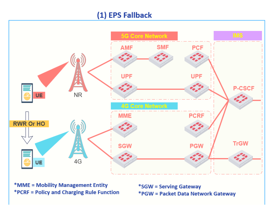
In simpler terms, EPS stands for Evolved Packet System, the core network in 4G. EPS Fallback in 5G means the device switches from the 5G core to the 4G core.
- EPS Fallback can be triggered when a UE initiates an IMS voice call while connected to the 5G Core Network using New Radio (NR).
- It requires the 5G Core Network to have connectivity to an IP Multimedia Subsystem (IMS) so the SIP signaling procedures can be initiated while the UE is connected to the NR Radio Access Network.
- The fallback procedure moves the UE onto a 4G Core Network using EUTRA. The 4G Core Network also has connectivity to the IMS so the voice call setup can then be completed.
- EPS Fallback avoids the 5G system having to support a QoS Flow with 5QI = 1, i.e. the 5G system can focus upon providing non-real time data services.
- In addition, the EUTRA Radio Access Network is likely to have wider coverage than the NR Radio Access Network (at least during early deployment) so it`s preferred at the initial stage of 5G Standalone network to use setup IMS Voice calls on the 4G Network.
The general network architecture for EPS Fallback is illustrated in the below Figure. (Call flow will be covered later in this article)
(2) RAT Fallback:
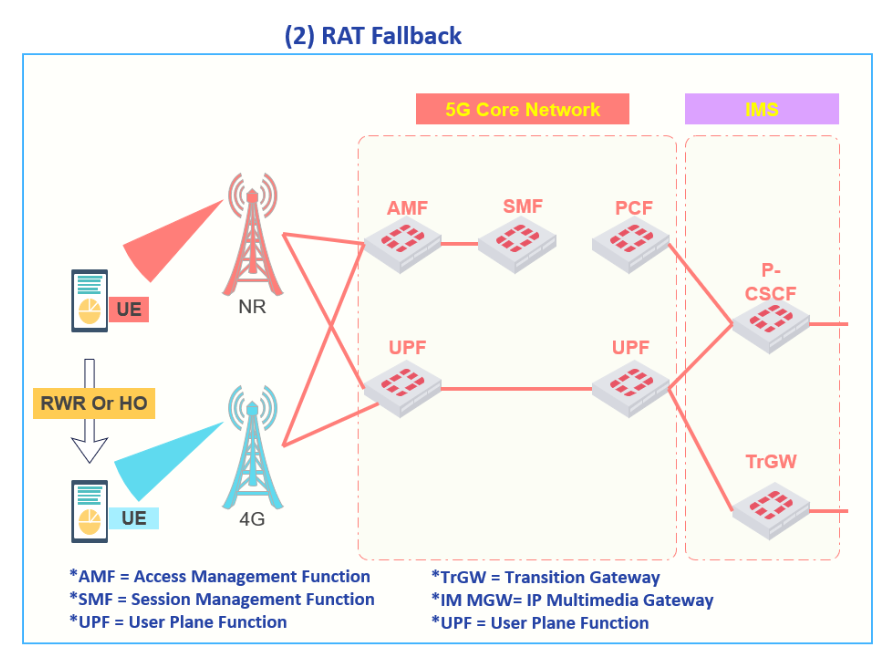
In simpler terms, in this triggering method, both 4G and 5G are connected to the 5G Core network. RAT Fallback, in this case, means that the user will shift from 5G RAN to 4G RAN under the same 5G Core. That's why it's called Radio Access Technology (RAT) Fallback.
- RAT Fallback can be triggered when a UE initiates an IMS voice call while connected to the 5G Core Network using New Radio (NR).
- It requires the 5G Core Network to have connectivity to an IP Multimedia Subsystem (IMS) so the SIP signaling procedures can be initiated while the UE is connected to the NR Radio Access Network.
- The fallback changes the Radio Access Network from NR to EUTRA while maintaining connectivity to the 5G Core Network. RAT Fallback avoids the NR Base Station having to support QoS Flows with 5QI = I. In addition, EUTRA Base Stations may provide better coverage than NR Base Stations - typically due to lower operating bands and larger site numbers during early NR deployment
- The IMS voice call setup procedure then continues on EUTRA in combination with the 5G Core Network. In this case, it is not possible to trigger an SRVCC towards 2G nor 3G when the system is based upon the release 15 version of the specifications.
The general network architecture for the RAT Fallback is illustrated in the Figure below.
Notes:
- An SRVCC from 5G towards 3G is planned for the release 16 version of the specifications.
- The signaling flow associated with RAT Fallback is similar to the signaling flow associated with EPS Fallback which will be explained in this article.
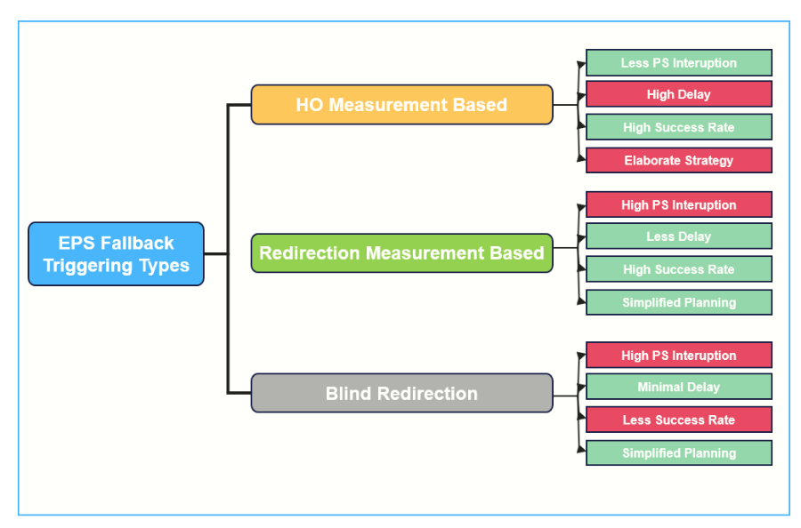
EPS Fallback Triggering Methods: Detailed exploration of the main triggering methods for Fallback.
- The Base Station is responsible for deciding to apply the EPS Fallback procedure. However, the g-NB controls the EPS Fallback triggering mechanism to be followed by the UE.
- So, what are the EPS Fallback triggering methods supported in 5G?
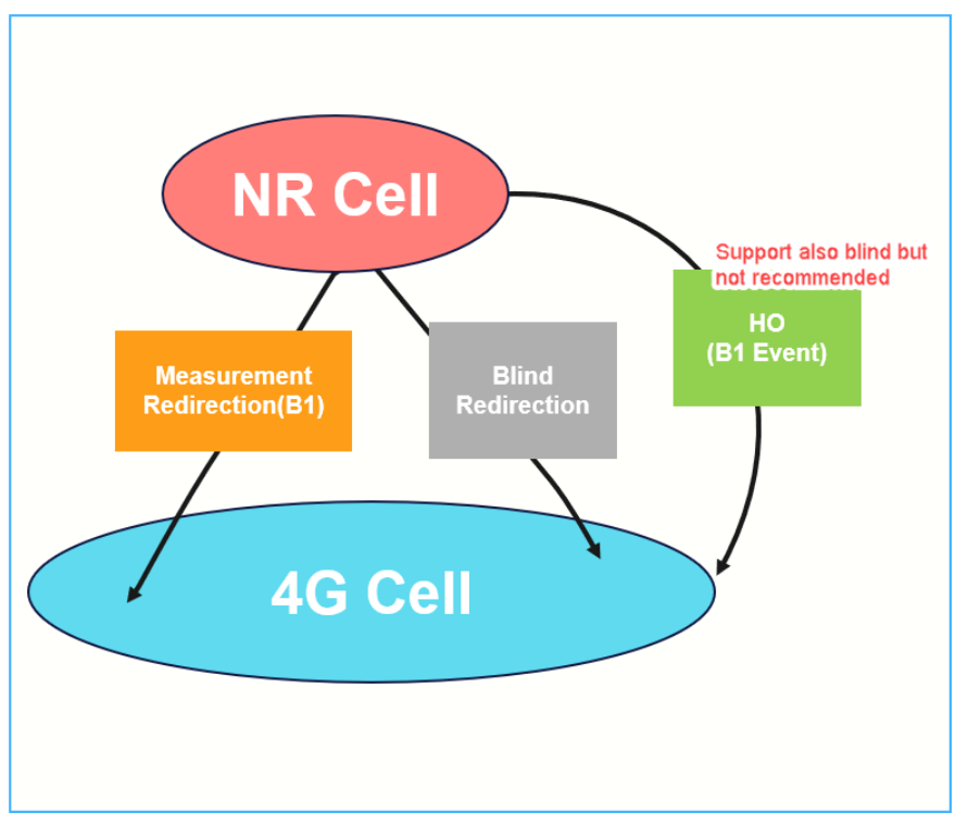
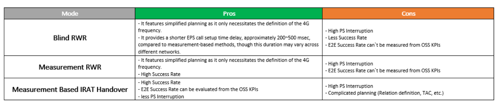
EPS Fallback supports two types of triggering methods: Handover or RRC Release with redirection (RWR). Both can be based on measurement or blind-based, but the handover part is usually used with measurements. It's not recommended to use a blind handover procedure without measurements.
Now, lets go through the details of EPS Fallback triggering mechanisms.
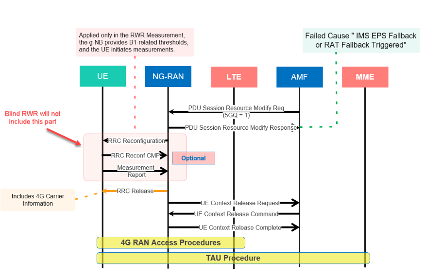
1- RRC Release with Redirection EPS Fallback (Blind & Measurement)
- As shown in the below Signaling call flow, An RRC Release with Redirection uses the RRC Release message to specify a target carrier. This procedure does not specify a target cell.
- In the case of Blind Release with redirection, the g-NB will guide the UE to the 4G network, specifying a designated LTE frequency. If multiple frequencies are defined, the g-NB will choose the frequency based on the defined voice priority, delivering the one with the highest priority to the UE.
- In the case of Measurement Release with redirection, the g-NB initially sends the RRC Reconfiguration message, incorporating B1-related events, to the UE. Subsequently, the UE commences measuring the reported 4G frequencies in the RRC Reconfiguration message, reporting the measurements to the g-NB through a Measurement Report. The g-NB then will redirect the UE to the reported LTE Frequency.
*You can find a detailed signaling call flow in 3GPP TS 23.502, illustrating NR to 4G IRAT Redirection with N26 Interface Procedures
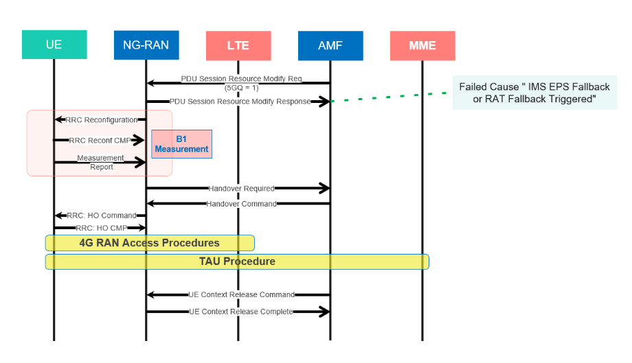
2- Measurement Based IRAT Handover EPS Fallback
- A handover uses the RRC Reconfiguration message to specify a target cell. Handover procedures usually take advantage of measurements to identify the target cell but it is also possible to use a blind handover procedure without measurements
*You can find a detailed signaling call flow in 3GPP TS 23.502, illustrating NR to 4G IRAT Handover with N26 Interface Procedures
Pros Vs Cons:
Notes:
- If the UE is moved to the 4G network using a handover then the UE completes a Tracking Area Update upon arrival. Similarly, the UE completes a Tracking Area Update if the UE is moved using an RRC Release with Redirection and there is an N26 interface between the AMF and MME.
- If the UE is moved to the 4G network using an RRC Release with Redirection and there is no N26 interface, then the UE completes an Attach procedure.
- The IMS voice call setup procedure then continues on 4G. Once the EPS Bearer with QCI - I has been setup, it is possible to trigger an SRVCC towards 2G or 3G.
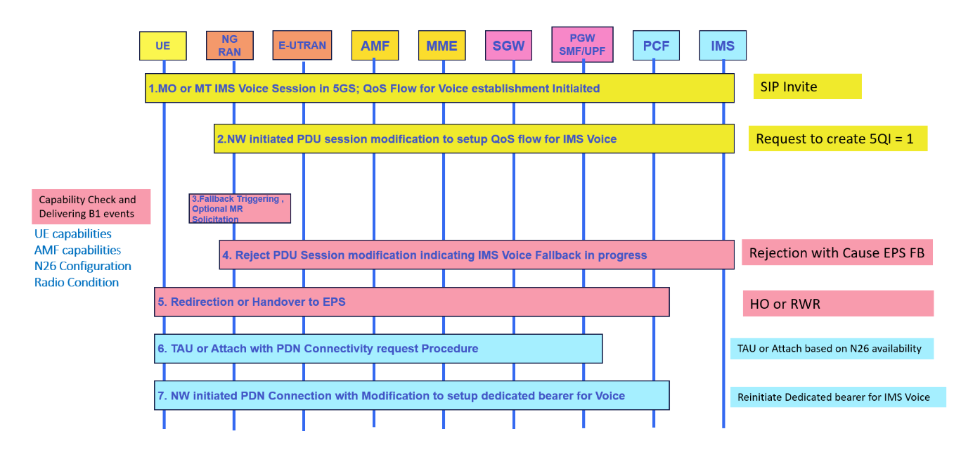
General Signaling Flow for EPS Fallback
- UE camps on NG-RAN in the 5GS and an MO or MT IMS Voice session establishment has been initiated.
- Network initiated PDU Session modification to setup QoS flow for IMS voice reaches the source NG-RAN.
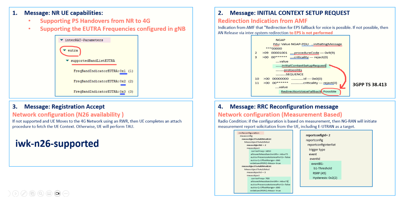
- NG-RAN is configured to support EPS fallback for IMS voice and decides to trigger fallback to EPS, taking into account UE capabilities, indication from AMF that "Redirection for EPS fallback for voice is possible" (received as part of initial context setup), network configuration (e.g. N26 availability configuration) and radio conditions. If NG-RAN decides not to trigger fallback to EPS, then the procedure stops here and following steps are not executed.NG-RAN may initiate measurement report solicitation from the UE including E-UTRAN as target.NOTE 1 : If AMF has indicated that "Redirection for EPS fallback for voice is not possible", then AN Release via inter-system redirection to EPS is not performed in step 5.
- Source NG-RAN responds indicating rejection of the PDU Session modification to setup QoS flow for IMS voice received in step 2 by PDU Session Response message towards the SMF via AMF with an indication that mobility due to fallback for IMS voice is ongoing. The SMF maintains the PCC rule(s) associated with the QoS Flow(s).
- NG-RAN responds indicating rejection of the PDU Session modification to setup QoS flow for IMS voice received in step 2 by PDU Session Modification Response message towards the SMF via AMF with an indication that mobility due to fallback for IMS voice is ongoing. The SMF maintains the PCC rule(s) associated with the QoS Flow(s) and reports the EPS Fallback event to the PCF if PCF has subscribed to this event.
- NG-RAN initiates either handover or AN Release via inter-system redirection to EPS, taking into account UE capabilities. The PGW-C+SMF reports change of the RAT type if subscribed by PCF as specified in clause 4.11.1.2.1, or clause 4.11.1.3.2.6. When the UE is connected to EPS, either 6a or 6b is executed
6.a In the case of 5GS to EPS handover and in the case of inter-system redirection to EPS with N26 interface. In either case the UE initiates TAU procedure; or
6.b In the case of inter-system redirection to EPS without N26 interface. If the UE supports Request Type flag "handover" for PDN connectivity request during the attach procedure and has received the indication that interworking without N26 is supported, then the UE initiates Attach with PDN connectivity request with request type "handover"
Network & UE Capability Check
According to 3GPP TS 23.502,
If NG-RAN is configured to support EPS fallback for IMS voice and decides to trigger fallback to EPS, the following is taken into account
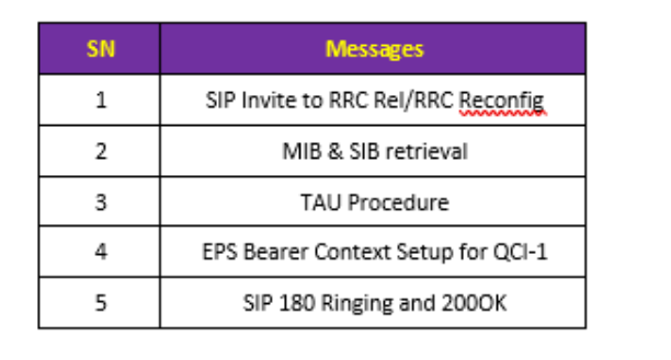
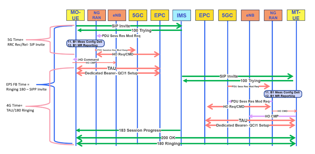
How to Calculate the EPS Fallback Setup Time?
- For Mobile Originating calls, EPS can be calculated from the SIP Invite until the Ringing (180) stage.
- For Mobile Terminating calls, if early alerting is enabled, you might need to calculate from the SIP Invite until the 200 OK or dedicated bearer activation.
The table below summarizes the steps involved during EPS Fallback call setup.
EPS Fallback Failures Common issues
- 5G Initial Access problems arise when a call is initiated from Idle Mode, such as RACH issues or when the UE doesn't respond to UE Capability and Security Commands.
- Similar to Volte, there are Race Conditions issues caused by signaling interference or conflicts with other procedures. For instance, if g-NB receives the PDU Modification request message from SMF while g-NB/UE initiates intra-Freq HO or 5G RWR to 4G.
- Paging issues may occur when the Mobile Terminating UE doesn't receive the paging request from AMF. This can result from radio problems or the need for AMF/RAN Paging strategy tuning.
- In 4G, RF issues may surface once the user is redirected to 4G. If 4G has poor coverage, it can lead to EPS Fallback failures.
Youtube Video for the same
Study Sources:
3GPP References: TS 23.501, TS 23.502, TS 38.413, TS 38.331
5G NR in Bullets(Page 511 to 521)
Practical experience


