What are 5G CSI-RS's Main Functions❓

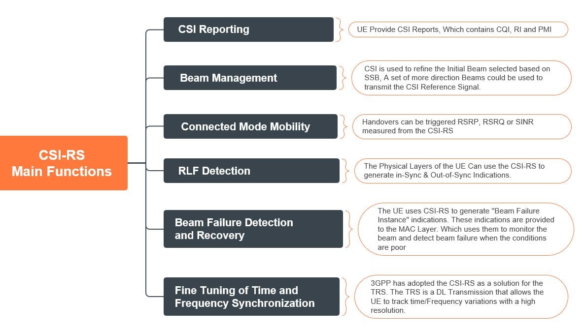
The Channel State information (CSI) Reference Signal is a multi-purpose DL Transmission. The Base Station can configure the UE to use the CSI-RS for one or more of the following:
1- CSI Reporting
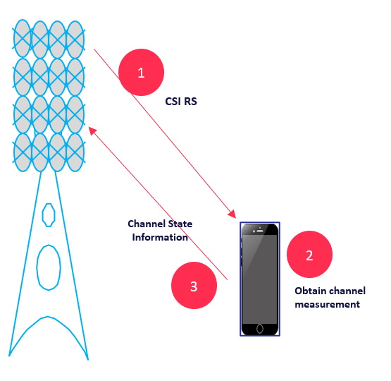
As seen in the below figure, the g-NB initially will send the related configuration and transmit CSI RS in the Downlink; then the UE will decode the corresponding CSI RS to obtain channel measurement after the UE reports the so-called Channel start information(CSI)
The UE reports Channel State Information (CSI) to the Base Station using either the PUSCH or the PUCCH; the Base Station uses the CSI to support its downlink transmissions on the PDSCH and PDCCH and CSI report Includes the following:
- Channel Quality Indicator (CQI)
- CSI-RS Resource Indicator
- Rank Indicator
- Layer Indication (LI)
- Precoding Matrix Indicator( PMI)
- L1-RSRP
- SS/PBCH Block Resource Indicator (SSBRI)
2- Beam Management “Refinement.”
- Once a UE has entered RRC Connected mode, it is possible to initiate Beam Refinement procedures.
- These procedures can select more directional beams with higher gain. More directional beams can improve the link budget.
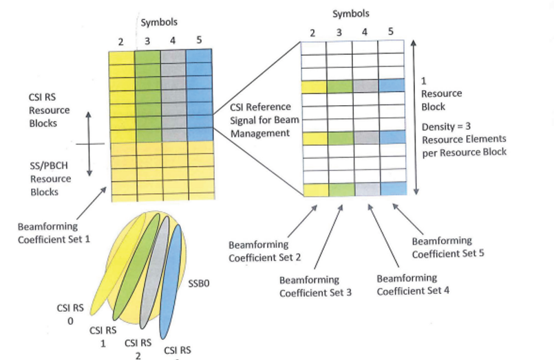
- The CSI Reference Signal can be used to support Beam Refinement procedures. For example, As shown in the below figure, a set of 4 CSI Reference Signal resources can be associated with each SS/PBCH Block
- a Total of 32 CSI Reference Signal resources would be configured using the maximum of 8 SS/PBCH Blocks in Frequency Range 1.
- The Base Station can apply different beamforming coefficients to each CSI Reference Signal resource to generate 4 directional beams per SS/PBCH Block. Each set of 4 CSI Reference Signals can be time multiplexed across four symbols and frequency multiplexed with the associate SS/PBCH Block.
- The below figure illustrates a set of 4 CSI Reference Signals that use the Resource Blocks above an SS/PBCH Block.
*Picture Source: 5G NR in Bullets
3- Connected Mode Mobility
Handovers can be triggered RSRP, RSRQ, or SINR measured from the CSI-RS.
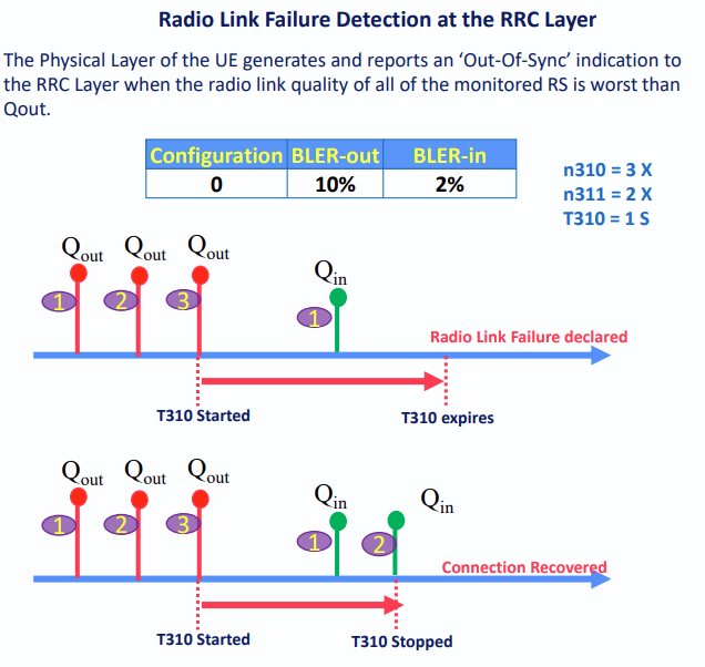
4- Radio Link Failure Detection(RLF)
The Physical Layers of the UE Can use the CSI-RS to generate in-Sync & Out-of-Sync Indications.
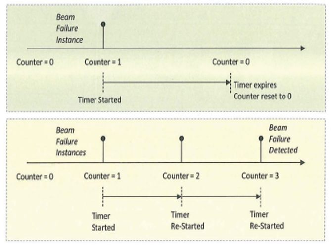
5- Beam Failure Detection and Recovery
The UE uses CSI-RS to generate ''Beam Failure Instance" indications. These indications are provided to the MAC Layer, which uses them to monitor the beam and detect beam failure when the conditions are poor.
*Picture Source: 5G NR in Bullets
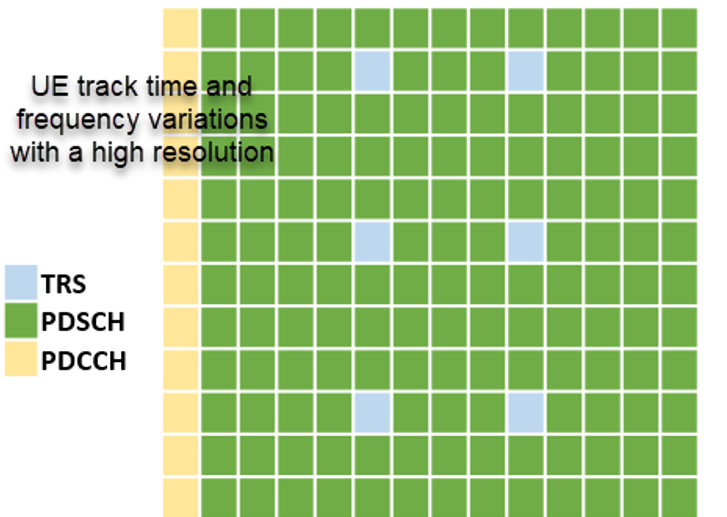
6- Fine Tuning of Time and Frequency Synchronization
3GPP has adopted the CSI-RS as a solution for the TRS. The TRS is a DL Transmission that allows the UE to track time/Frequency variations with a high resolution.
*Some of the Procedures listed above can also be completed using SS/PBCH block measurements. For Example, Connected Mode Mobility, RLF detection, and Beam Failure detection
Refer to the below YouTube video for more details:
Data Source:
- 5G NR in Bullets